Dust Collector Airflow and CFM Requirements: How Much Do You Need?

Choosing the right industrial dust collector is not just about selecting a unit with a high filtration efficiency. The system must also move enough air to capture dust at the source, transport it through the ductwork, and maintain effective collection under actual operating conditions.

This is where dust collector airflow becomes a critical design consideration. Too little airflow can allow dust to escape into the workplace or settle inside ductwork. Excessive airflow, on the other hand, can increase energy consumption, operating costs, and filter loading without necessarily improving dust capture.

For industrial facilities, determining the right airflow requires an understanding of the dust-generating process, extraction hood design, duct dimensions, conveying velocity, and the resistance created by filters and other system components.

This guide explains how to calculate dust collector CFM requirements, estimate the airflow needed for different industrial applications, and avoid common sizing mistakes.

What Is Dust Collector Airflow?

Dust collector airflow is the volume of air moved through a dust collection system over a specified period. It is commonly expressed in cubic feet per minute (CFM) or cubic metres per hour (m³/hr).

Airflow determines how much contaminated air the system can draw through its capture points. However, the required airflow depends on the application rather than on the collector alone.

For example, a small sanding station may require a different airflow arrangement from a grinding machine, a woodworking process, or a production line handling fine powder.

Three related factors must be considered when designing a dust collection system:

  1. Capture airflow: The airflow needed to draw dust into the hood or extraction point before it spreads into the workplace.
  2. Duct conveying velocity: The air velocity required to transport collected dust through the ductwork without excessive settling or accumulation.
  3. Collector operating airflow: The airflow the fan must deliver through the complete system, accounting for ductwork, filters, hoods, and other resistance.

These factors are related, but they are not interchangeable. A dust collector with a high advertised airflow may still provide insufficient capture at a poorly designed extraction hood.

What Is CFM in Dust Collection?

CFM stands for cubic feet per minute. It measures the volume of air moving through a dust extraction system every minute.

The term dust collector CFM is often used when comparing industrial dust collectors, but the number must be interpreted in the context of the system’s operating conditions.

A collector rated for a particular maximum CFM may deliver less airflow when connected to ductwork and filters that create resistance. Filter loading can also increase pressure drop and affect the airflow available at the extraction points.

CFM can be converted to cubic metres per hour using the following relationship:

1 CFM ≈ 1.699 m³/hr

For example:

Airflow (CFM) Approximate airflow (m³/hr)
250 425
500 850
1,000 1,699
1,500 2,549
2,000 3,398
3,000 5,097

These figures are unit conversions, not recommended airflow values for specific industrial applications. Actual requirements must be calculated from the process and system design.

Why Is Correct Dust Collection Airflow Important?

Correct dust collection airflow affects both the performance and operating cost of an industrial dust extraction system.

1. Effective Dust Capture

Dust generated during grinding, cutting, polishing, sanding, and material handling can disperse quickly. The extraction hood must draw contaminated air into the system before the dust escapes into the surrounding area.

If airflow is insufficient for the hood geometry and source conditions, visible dust may escape even when the collector’s filters are suitable for the application.

2. Reliable Dust Transport Through Ductwork

Once dust enters the extraction system, the airflow must transport it through the ducts to the collector.

If conveying velocity is too low for the dust being handled, material may settle in horizontal ducts or accumulate at bends and branches. The appropriate velocity depends on particle characteristics, material loading, moisture content, and duct configuration.

3. Consistent System Performance

In a multi-point dust collection system, each extraction point needs an appropriate share of the available airflow. Poorly balanced ductwork can cause some machines to receive adequate extraction while others perform poorly.

A correctly designed system considers the operating requirements of individual branches as well as the total airflow required by the collector.

4. Energy and Operating Costs

Moving air requires energy. Oversizing the fan or operating at unnecessarily high airflow can increase power consumption, noise, and operating costs.

The objective is not to maximize CFM. It is to deliver the airflow required for effective capture and transport at the pressure conditions of the system.

How to Calculate Dust Collector CFM Requirements

The airflow calculation depends on whether you are sizing a single extraction point or an entire industrial dust collection system.

Step 1: Determine the Airflow Required at Each Extraction Point

For each machine or process, identify the capture arrangement and the airflow needed to control dust generation.

Relevant factors include:

  1. The type and intensity of the dust-generating operation.
  2. The size and geometry of the extraction hood.
  3. The distance between the hood and the dust source.
  4. Whether the process is enclosed or open.
  5. The direction and speed of dust generation.
  6. The number of extraction points connected to the system.

For an enclosed machine, airflow may be determined by the enclosure openings and the required inward air movement. For an open grinding or polishing operation, hood geometry and source-capture requirements become particularly important.

Avoid assigning the same CFM to every machine simply because the machines are located in the same factory.

Step 2: Add the Airflow Requirements of Simultaneously Operating Points

For a system serving several extraction points, the initial total airflow requirement can be estimated by adding the airflow required at each point expected to operate simultaneously.

The basic relationship is:

Total airflow = Sum of the required airflow at simultaneously operating extraction points

For example, suppose a system serves four machines, each requiring an illustrative 500 CFM at its extraction point.

If all four machines operate simultaneously, the combined nominal requirement is 2,000 CFM.

If only two machines are intended to operate at a time, the operating demand may be lower, but this should only be used when the operating controls and production procedures reliably prevent additional branches from opening.

This calculation establishes an initial airflow requirement. It does not complete the system design.

Step 3: Check Duct Conveying Velocity

The ductwork must transport the dust without unacceptable accumulation.

For a round duct, the relationship between airflow, duct area, and air velocity is:

[
Q = V x A
]

Where:

  1. (Q) is volumetric airflow.
  2. (V) is average air velocity.
  3. (A) is the duct’s internal cross-sectional area.

When airflow is expressed in cubic feet per minute and velocity in feet per minute, the area is expressed in square feet.

The equation can be rearranged to estimate the airflow needed for a chosen duct velocity:

[
CFM = Velocity (ft/min) x Area (ft}^2
]

For example, a 6-inch-diameter round duct has an internal area of approximately 0.196 square feet. At an illustrative air velocity of 4,000 ft/min, the corresponding airflow is approximately 785 CFM.

This is a mathematical example, not a universal design recommendation. The appropriate conveying velocity must be selected for the material being transported and the system’s operating conditions.

Step 4: Calculate System Static Pressure

After establishing the airflow requirements, determine the resistance the fan must overcome.

Static pressure losses can arise from:

  1. Extraction hoods and inlet openings.
  2. Straight duct sections.
  3. Bends, elbows, and branch connections.
  4. Dampers and other fittings.
  5. Filter media.
  6. Collector inlets and outlets.
  7. Exhaust ductwork, where applicable.

The fan must deliver the required airflow at the calculated operating static pressure. Selecting a fan using only its maximum or free-air CFM rating can result in inadequate airflow after installation.

For multi-point systems, the design should evaluate the most demanding airflow path and ensure that each branch receives its required flow.

Step 5: Account for Filter Loading and Operating Conditions

As dust accumulates on filter media, the pressure drop across the filters may increase. The fan and filtration system must be suitable for the expected operating range.

Designers should establish the airflow and pressure conditions at which the system is expected to operate, along with the criteria for filter cleaning or replacement.

A system that meets its airflow requirement with clean filters but cannot maintain adequate extraction as filters load may not be suitable for continuous industrial production.

Typical Dust Collector Airflow Requirements by Application

Airflow requirements vary considerably with machine design, dust generation rate, hood geometry, enclosure, and operating conditions. The following table provides qualitative guidance rather than fixed CFM recommendations.

Industrial application Main airflow consideration
Grinding machines Hood position, wheel size, dust trajectory, and enclosure
Polishing and buffing Capture arrangement around the workpiece and wheel
Cutting operations Dust generation rate, enclosure, and cutting method
Sanding Hood design, surface area, and the rate of dust generation
Deburring Workpiece geometry and the location of dust release
CNC machining Process enclosure and the characteristics of generated particulate matter
Powder handling Material properties, transfer-point enclosure, and containment
Foundry operations Process-specific emissions, thermal conditions, and capture arrangements
Multiple fabrication machines Combined airflow demand, branch balancing, and simultaneous usage

These applications should not be sized using a single generic CFM value. The required airflow must be determined from the machine manufacturer’s recommendations, accepted engineering guidance, and the actual extraction arrangement.

For example, a grinding machine with a well-designed enclosure may need a different airflow from an open grinding station performing a similar operation. The machine layout and capture method can materially affect the requirement.

Dust Collector Airflow vs. Duct Air Velocity

Airflow and air velocity are often confused, but they describe different properties.

Airflow is the volume of air moving through the system per unit of time.

Air velocity is the speed at which the air moves through a duct or opening.

A larger duct can carry the same airflow at a lower velocity than a smaller duct. This is why duct diameter must be considered alongside CFM when designing dust collection airflow.

If the duct is too large for the selected airflow, conveying velocity may be inadequate for the dust being transported. If the duct is too small, resistance may increase substantially, raising fan requirements and potentially reducing the airflow available at the extraction hood.

The correct duct size is therefore determined by balancing required airflow, material-appropriate conveying velocity, pressure losses, and practical installation constraints.

How to Size Airflow for a Centralized Dust Collection System

Centralized dust collection systems connect several machines or extraction points to a common filtration unit.

Sizing these systems requires more than adding up the maximum airflow ratings of all connected machines. The design must establish which branches operate together, the airflow required at each branch, and how the duct network distributes air.

A sound design process typically includes the following:

  1. Map every extraction point. Record the machines, hood types, duct connections, and operating requirements.
  2. Establish simultaneous demand. Determine which machines can operate at the same time and whether operating controls reliably manage that demand.
  3. Design the duct network. Select duct dimensions and branch configurations to deliver the required airflow while maintaining suitable conveying velocity.
  4. Calculate pressure losses. Account for the most demanding airflow path through the ductwork, fittings, and filtration equipment.
  5. Select the fan and collector. Confirm that the equipment can deliver the required airflow at the calculated operating pressure.
  6. Provide for balancing and verification. Include suitable provisions for adjusting and measuring airflow at individual branches.

Airflow controls can help manage systems with variable demand, but they must be designed around the actual operating requirements. Simply closing unused branches or reducing fan speed without verification can compromise capture at active stations.

How Filter Type Affects Dust Extraction Airflow

The filtration system influences the resistance the fan must overcome, making filter selection an important part of airflow design.

Non-Woven Polyester Filters

Non-woven polyester filter media can be used in suitable industrial dust collection applications, depending on the particle characteristics and operating conditions.

Powertech’s DustBag industrial dust collector is designed for industrial dust extraction applications. Its suitability for a particular process should be assessed against the dust type, required airflow, filtration specifications, and operating conditions.

Reverse-Pulsed-Jet Filtration

Reverse-pulsed-jet systems use compressed-air pulses to dislodge accumulated dust from compatible filter elements. This cleaning arrangement can support continuous operation in applications where dust loading and filter characteristics are appropriate.

The cleaning system does not eliminate the need to size the fan and filtration equipment correctly. Airflow, pressure drop, dust properties, and cleaning requirements must all be considered when selecting the collector.

Why Filter Selection Matters

The appropriate filter depends on particle characteristics, dust loading, temperature, moisture, chemical compatibility, and the required collection performance.

A filter’s nominal efficiency alone does not establish the overall performance of the system. Capture effectiveness, filter sealing, operating airflow, maintenance, and the properties of the dust also matter.

Where dust presents a combustible, toxic, or otherwise hazardous risk, the system may require additional engineering controls and a specialized risk assessment.

Common Mistakes When Calculating Dust Collector CFM

1. Selecting a Collector Based Only on Maximum CFM

A maximum airflow rating may not represent the airflow available after connecting the ductwork and filters. Always evaluate the fan’s performance at the expected operating static pressure.

2. Ignoring Hood Design

A large collector cannot compensate for a poorly positioned or badly designed extraction hood. Dust may escape before it reaches the system, regardless of the filter’s efficiency.

3. Using the Same Airflow for Every Machine

Grinding, polishing, powder handling, and enclosed machining operations have different capture and transport requirements. Airflow should be based on the application.

4. Overlooking Duct Velocity

The system must maintain appropriate velocity for the dust being transported. Insufficient conveying velocity may lead to accumulation, while excessive velocity can increase pressure losses and wear.

5. Ignoring Filter Loading

Airflow should be evaluated under realistic operating conditions, including the expected pressure drop across the filters.

6. Oversizing the System Without Engineering Justification

Excessive airflow can increase fan energy consumption and operating costs. A correctly sized system delivers the airflow needed for effective capture and transport without unnecessary capacity.

7. Failing to Verify Installed Performance

After installation, airflow should be measured and adjusted as needed. Verification helps confirm that the system delivers the intended performance at the actual extraction points.

Practical Dust Collector Airflow Calculation Checklist

Before selecting an industrial dust collector, establish the following information:

  1. Dust-generating processes and materials identified.
  2. Extraction hood and enclosure requirements documented.
  3. Required airflow at each capture point established.
  4. Simultaneously operating machines identified.
  5. Duct diameters and material-appropriate conveying velocities determined.
  6. Pressure losses across ducts, fittings, and filters calculated.
  7. Fan performance checked at the required operating static pressure.
  8. Filter specifications and expected loading considered.
  9. Maintenance and filter-cleaning arrangements defined.
  10. Airflow measurement and commissioning requirements established.

These details provide a stronger basis for selecting a collector than comparing equipment by CFM alone.

Conclusion

Determining the right dust collector airflow requires a system-level approach. CFM establishes how much air must move through the system, but effective dust collection also depends on capture hood design, duct velocity, static pressure, filtration, and operating conditions.

For a single machine, the airflow requirement should be established at the extraction point. For a centralized installation, the design must also account for simultaneous demand, duct network resistance, and airflow distribution across all connected branches.

Powertech Pollution Controls provides industrial dust collection solutions for manufacturing and material-processing applications. When evaluating a suitable system, share the dust-generating process, number of extraction points, operating schedule, layout, and available technical specifications so that the airflow and filtration requirements can be assessed.

The goal is not simply to purchase a dust collector with a high CFM rating. It is to design a system that delivers the required airflow where it is needed and maintains effective performance under real operating conditions.
Industrial Welding Fume Extractor: Applications, Design and Selection

Welding is a critical operation in fabrication shops, automotive manufacturing, heavy engineering, infrastructure production, and metalworking industries. However, welding also generates fumes containing fine particles and metal oxides, along with gases that vary according to the welding process, base material, filler metal, and consumables used.

In an industrial environment, these emissions can spread beyond individual workstations, affecting operator exposure, workplace air quality, and the cleanliness of the production area. An industrial welding fume extractor helps control these emissions by capturing fumes near their source and passing the contaminated air through an appropriate filtration system.

Selecting the right equipment involves more than choosing a unit with sufficient airflow. Manufacturers must consider welding processes, the number of workstations, production volume, capture arrangements, filtration requirements, and future expansion.

This guide explains how industrial welding fume extraction systems work, where they are used, how they should be designed, and what to evaluate before purchasing one.

What Is an Industrial Welding Fume Extractor?

An industrial welding fume extractor is an air pollution control system designed to capture and filter fumes generated during welding operations. Depending on the application, it may serve a single welding station, several workstations, or an entire production area.

A typical system includes:

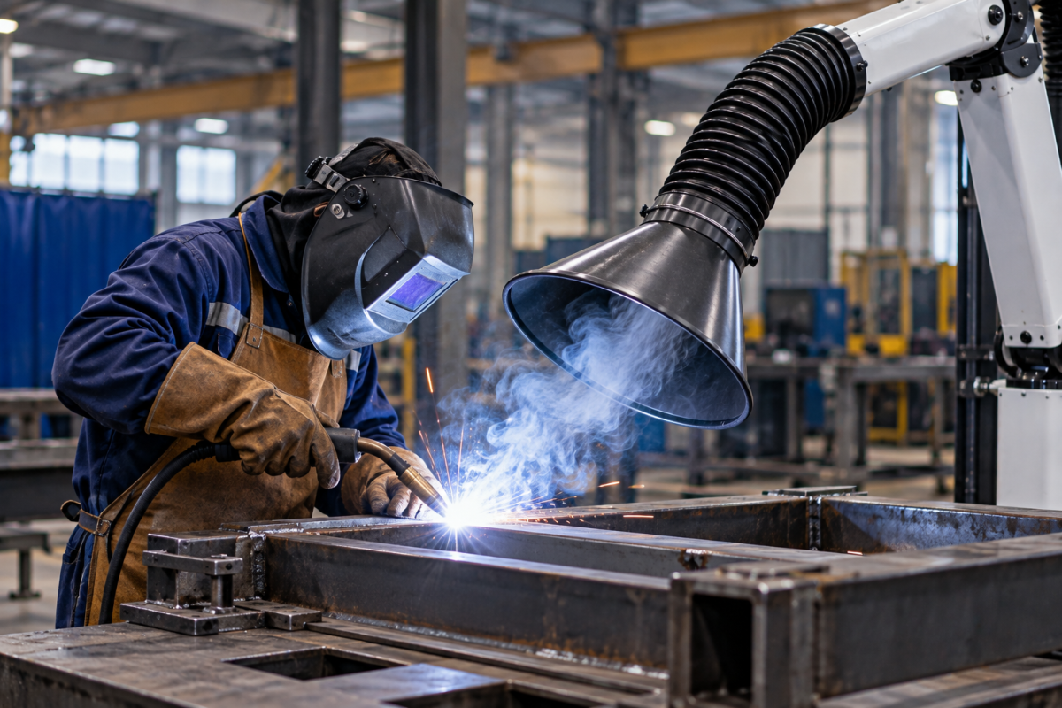
  1. Fume capture equipment: Extraction arms, hoods, enclosures, or integrated capture points positioned near the welding process.
  2. Air movement equipment: A fan or blower that draws contaminated air into the system.
  3. Filtration equipment: Filters selected to capture the particulate matter generated by the application.
  4. Ductwork, where required: A network that transports contaminated air from multiple capture points to a central filtration unit.
  5. Controls and monitoring: Components that help maintain operating conditions and identify performance problems.

The system’s effectiveness depends on how these components work together. Even a high-capacity filtration unit may perform poorly if fumes escape before reaching the capture point or if the ductwork does not deliver the required airflow.

For a broader understanding of the available equipment configurations, an industrial welding fume extraction system should be evaluated according to the welding process, workspace layout, and expected operating conditions.

Why Is Industrial Welding Fume Extraction Important?

Welding fumes form when materials heated during welding vaporize and subsequently condense into fine airborne particles. Their composition depends on factors such as the metal being welded, electrode or filler material, coatings, shielding gases, and welding technique.

Stainless steel welding, for example, can generate fumes containing chromium and nickel compounds. Other welding applications may produce iron oxides, manganese-containing particles, or additional contaminants depending on the materials and consumables involved.

Effective extraction helps control these emissions before they disperse throughout the workplace.

Industrial welding fume extraction can support several operational objectives:

Reducing worker exposure: Capturing fumes close to the welding point helps limit the amount of airborne contamination reaching the operator’s breathing zone.

Improving workplace air quality: Source capture reduces the release of welding fumes into the surrounding production environment.

Maintaining cleaner equipment and work areas: Effective collection can reduce the deposition of airborne particulate matter on nearby surfaces and machinery.

Supporting workplace safety programmes: Properly designed extraction can form part of a broader occupational exposure-control strategy, alongside suitable work practices, exposure assessment, and other protective measures where necessary.

The NIOSH guidance on welding fumes and applicable occupational safety requirements can help businesses evaluate exposure-control measures for their particular welding operations.

Common Industrial Applications of Welding Fume Extractors

Different industries generate welding fumes under different operating conditions. Equipment selection should reflect the scale of production, the geometry of the workpieces, and how easily the capture point can be positioned.

1. Metal Fabrication and Manufacturing

Fabrication shops perform activities such as structural welding, sheet-metal fabrication, equipment manufacturing, and the assembly of metal components. Workpieces can vary significantly in size, and welding stations may change according to production requirements.

Flexible extraction arms, movable capture hoods, and portable extraction units can be suitable for selected applications where the operator can position the capture point close to the welding arc.

For facilities with multiple welding bays, a more coordinated system may be required. The design should account for station usage, workpiece dimensions, and the potential for fumes to escape when operators move around large components.

2. Heavy Fabrication and Structural Welding

Heavy fabrication involves large structures, frames, equipment housings, and other components that may require welding from several positions.

In these environments, a fixed hood may not consistently capture fumes from every weld location. Extraction arms with adequate reach, movable capture equipment, or purpose-designed local enclosures may offer greater flexibility.

Where operator mobility and changing workpiece positions are major concerns, the system should be selected around the actual welding workflow. The practical considerations involved in welding fume extraction for fabrication shops are especially relevant to these installations.

3. Automotive and Component Manufacturing

Automotive manufacturing and component production may involve repeated welding operations, dedicated fixtures, robotic cells, and multiple production stations.

Manual welding stations may use local capture equipment, while automated welding cells may be better suited to extraction integrated with the enclosure or designed around the location of the emissions.

For automated applications, designers should consider the welding cycle, enclosure openings, robot movement, and the airflow needed to capture fumes without interfering with the process.

4. Stainless Steel Welding

Stainless steel welding requires particular attention to fume composition because the emissions may contain chromium and nickel compounds, depending on the alloy and welding conditions.

An industrial welding fume extractor for these applications should be selected using an assessment of the materials, consumables, welding technique, and applicable exposure-control requirements.

Filtration specifications should be evaluated alongside capture performance. Selecting a filter based only on a general particle-size claim is insufficient to establish that the overall installation will adequately control worker exposure.

5. Robotic Welding and Automated Production

Robotic welding can produce concentrated fume emissions within a relatively defined work area. Depending on the cell design, extraction may be integrated into an enclosure, hood, or dedicated collection arrangement.

The system should accommodate the robot’s operating envelope, access for maintenance, and any openings through which fumes may escape.

The extraction design should also account for production demand and the number of robotic cells operating simultaneously. For facilities considering automation, robotic welding fume extraction should be assessed as part of the overall cell and ventilation design rather than as an isolated equipment purchase.

Industrial Welding Fume Extraction System Design

A reliable industrial welding fume extraction system starts with an assessment of the welding operation. The aim is to capture emissions effectively at the source and transport them to suitable filtration equipment without compromising production.

1. Assess the Welding Process

The first step is to document the welding processes used throughout the facility. MIG, TIG, stick, flux-cored, and other welding processes can generate different fume loads and contaminant compositions.

The assessment should also consider:

  1. Base metals and their coatings.
  2. Filler metals and electrode consumables.
  3. Welding current, duty cycle, and production rate.
  4. Workpiece dimensions and welding positions.
  5. Whether welding is manual, semi-automatic, or robotic.
  6. The number of stations operating simultaneously.

These details help establish the likely emissions profile and the most practical capture arrangement.

2. Choose the Capture Method

Source capture is generally the preferred starting point because it intercepts fumes before they disperse into the wider workspace.

Common capture arrangements include:

Extraction arms: Flexible arms with capture hoods that can be positioned near the welding arc. They are useful where welding positions and workpieces vary.

Fixed hoods: Suitable for repeatable operations where the capture position can be maintained consistently.

Enclosures and integrated extraction: Often appropriate for robotic welding cells or other processes that can be enclosed or partially enclosed.

Portable extraction units: May suit smaller operations or workstations where fixed ductwork is impractical, provided the unit has adequate capacity and the capture point can be positioned effectively.

Centralized extraction: Connects multiple capture points to a shared filtration unit through a designed duct network.

The right arrangement depends on the workpiece, operator movement, capture distance, and the way fumes travel away from the source. The system should not obstruct welding access or force operators into awkward working positions.

3. Calculate Airflow Requirements

Airflow requirements depend on the capture method, hood geometry, distance from the source, and operating conditions.

A system designed for a single welding station may have very different requirements from one serving several fabrication bays. For a centralized installation, designers must also consider simultaneous usage, branch airflow, duct resistance, and the effect of filter loading.

Airflow should therefore be calculated for the intended system configuration rather than selected from the fan’s maximum advertised capacity alone.

A practical design assessment should establish:

  1. Required airflow at each capture point.
  2. Number of capture points expected to operate together.
  3. Duct dimensions, lengths, bends, and branch connections.
  4. Pressure losses through the capture equipment and filters.
  5. Expected changes in resistance as filters load.
  6. Provisions for checking airflow during commissioning and routine operation.

Insufficient airflow can allow fumes to escape. Excessive airflow may waste energy, increase noise, or disrupt the welding operation. The goal is effective capture at each point under realistic operating conditions.

4. Evaluate Static Pressure and Fan Selection

Static pressure is the resistance the fan must overcome as air moves through the capture hood, ductwork, filters, and other system components.

A fan should be selected using the required airflow at the system’s expected operating pressure. Choosing equipment based only on motor power or free-air airflow can lead to an installation that fails to deliver the required performance once connected to the complete system.

For centralized systems, pressure losses should be evaluated across the entire duct network. Poorly designed branches or unsuitable duct dimensions can create uneven airflow, leaving some stations with inadequate extraction.

Fan selection and duct design should therefore be treated as connected engineering decisions.

Industrial Welding Fume Filtration: What Should You Consider?

After fumes are captured, the filtration system must be suitable for the contaminants being collected and the operating conditions of the facility.

Filter Selection

Welding fumes contain fine particulate matter, so the filtration equipment must be selected for the expected particle characteristics and required collection performance.

Depending on the application, an industrial dust collector with an appropriate filter configuration may be suitable for welding fume particulate collection. However, equipment designed for coarse grinding dust should not automatically be assumed to provide suitable welding fume filtration.

The design should account for filter efficiency, airflow resistance, dust loading, cleaning requirements, and the manufacturer’s stated operating limits.

Filter Cleaning and Maintenance

Welding fume filters accumulate particulate matter during operation. As the filters load, airflow resistance may increase, potentially reducing capture performance if the system is not designed and maintained appropriately.

Depending on the filter design and operating conditions, maintenance arrangements may include manual filter replacement, periodic cleaning, or automatic cleaning systems.

A reverse-pulsed-jet dust collection system may be worth evaluating for compatible industrial particulate applications. Its suitability for a particular welding fume installation must be confirmed against the filter specifications, contaminant characteristics, and manufacturer’s recommendations.

Filtration Efficiency Is Not the Same as Exposure Control

A high-efficiency filter does not, by itself, guarantee effective control of welding fumes throughout the workplace.

Overall performance also depends on capture efficiency, leakage, airflow distribution, maintenance, and the way the system is operated. Where required, exposure monitoring and suitable verification should be used to evaluate whether the installation achieves its intended control objectives.

Portable vs Centralized Industrial Welding Fume Extractors

One of the main purchasing decisions is whether to use individual extraction units or a centralized system.

Factor Portable or individual units Centralized extraction
Best suited to Selected individual stations and changing work locations Multiple workstations or larger production areas
Installation Usually simpler for a small number of points Requires engineered ductwork and system planning
Flexibility Units can often be relocated Capture points are generally connected to fixed infrastructure
Airflow management Managed at each unit Requires balancing across branches and capture points
Maintenance Units can be serviced individually Shared equipment requires coordinated maintenance
Expansion Additional units may be required Expansion depends on available fan, filter, and duct capacity
Space Equipment may occupy floor or workstation space Main filtration equipment can be located away from workstations

Portable systems can be practical for intermittent welding and isolated stations. Centralized extraction can be advantageous where several stations need to operate within a coordinated system.

The choice should be based on the number of welding points, their operating schedules, the required capture method, and the long-term operating cost—not solely on the initial equipment price.

How to Select the Right Industrial Welding Fume Extractor

Before comparing suppliers, establish the technical and operational requirements of the application.

1. Define the Number of Welding Stations

Record the number of workstations and determine how many are expected to operate simultaneously. For centralized systems, simultaneous demand has a direct impact on airflow and fan sizing.

2. Identify the Materials and Welding Processes

Document the metals, coatings, electrodes, filler materials, and welding processes used. This information helps establish the contaminant profile and the filtration requirements.

3. Assess Operator Mobility

Determine whether welding occurs at fixed benches, large fabricated structures, moving workpieces, or robotic cells. This will help identify suitable extraction arms, hoods, enclosures, or integrated capture arrangements.

4. Verify Airflow and Filtration Specifications

Ask suppliers to explain the required airflow, operating static pressure, filter configuration, expected maintenance requirements, and limitations of the proposed equipment.

Specifications should relate to the actual installation rather than only to standalone unit performance.

5. Consider Installation and Operating Costs

The purchase price is only one part of the total cost. Evaluate installation, ductwork, electricity consumption, filter replacements, servicing, downtime, and future expansion.

6. Check Serviceability and Spare Parts

Ensure the filtration equipment can be inspected and maintained safely, and that suitable replacement filters and service support are available.

7. Plan for Future Capacity

If the facility expects to add welding stations or increase production, consider whether the system can accommodate that demand. Expansion may require additional fan capacity, filtration capacity, ductwork, or revised airflow balancing.

Common Mistakes to Avoid

Industrial welding fume extraction systems can underperform when important design factors are overlooked.

Selecting a system by motor power alone: Motor rating does not establish the airflow available at the capture point.

Positioning extraction equipment too far from the welding arc: Fumes can disperse before they reach the capture hood.

Using one generic design for every welding process: Different materials, consumables, and welding techniques produce different emissions and operating requirements.

Ignoring ductwork design: Poorly designed duct networks can result in uneven airflow across multiple stations.

Choosing filtration without understanding the contaminant profile: Filter suitability must be established for the actual application.

Neglecting maintenance: Loaded or damaged filters and poorly maintained capture equipment can compromise system performance.

Assuming extraction eliminates every exposure risk: Extraction is one component of a broader exposure-control programme. Additional controls may be needed based on the process and exposure assessment.

Industrial Welding Fume Extractor Selection Checklist

Use this checklist when preparing a technical specification or requesting quotations.

  1. Welding processes and materials identified.
  2. Fume-generating operations and work locations documented.
  3. Number of stations and simultaneous usage established.
  4. Capture method selected for each application.
  5. Airflow and static pressure requirements calculated.
  6. Filtration configuration matched to the contaminants.
  7. Filter cleaning and replacement requirements documented.
  8. Installation space, duct routing, and access assessed.
  9. Energy consumption and ongoing maintenance considered.
  10. Future production expansion evaluated.
  11. Commissioning and performance-verification requirements defined.

Conclusion

An industrial welding fume extractor should be selected as an engineered air pollution control solution, not simply as a fan-and-filter unit.

The right system depends on the welding process, materials, capture arrangement, airflow requirements, filtration performance, and production layout. Smaller operations may be served by individual extraction units, while larger facilities may benefit from a centralized system designed around multiple welding stations.

By evaluating these factors before purchasing, manufacturers can make better-informed decisions about system performance, maintenance, operating costs, and long-term suitability.

Powertech Pollution Controls provides industrial air pollution control solutions for manufacturing applications. To evaluate a suitable welding fume extraction configuration, discuss your welding processes, number of stations, workstation layout, and filtration requirements with the technical team.

The final system design should be based on the application’s engineering requirements and verified performance expectations.

‘

How to Choose the Right Soldering Fume Extractor for Electronics Manufacturing

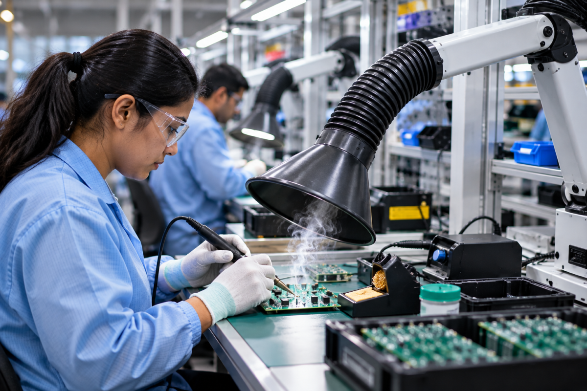
Soldering is an essential process in electronics manufacturing, from PCB assembly and component rework to high-volume production lines. However, soldering fumes can contain airborne particles and chemical compounds released when flux is heated. Without suitable extraction, these contaminants can accumulate around workstations and expose operators during routine production.

Choosing the right soldering fume extractor requires more than comparing motor ratings or filter specifications. The system must match the soldering process, flux chemistry, number of workstations, production volume, and required level of contaminant control.

This guide explains the key factors electronics manufacturers should evaluate when selecting a soldering fume extraction system.

1. Identify the Soldering Process and Fume Source

The first step is to identify where fumes are generated and how the soldering operation is performed. Different processes produce different fume loads and require different extraction arrangements.

Common applications include:

  1. Manual PCB soldering: Individual operators solder components at benches, often using hand-held soldering irons.
  2. PCB rework and repair: Operators remove or replace components, frequently working on localized areas of a circuit board.
  3. Wave soldering: Flux is applied before circuit boards pass over a wave of molten solder.
  4. Selective soldering: Automated equipment solders specific areas of a PCB.
  5. High-volume electronics assembly: Multiple workstations operate simultaneously, potentially requiring coordinated extraction across the production area.

For manual assembly and repair, a PCB soldering fume extractor may be suitable for capturing fumes close to the operator’s work area. Automated processes may require extraction integrated with the equipment enclosure or process hood.

The extraction method should be selected according to the actual source of emissions rather than assuming that one system will work equally well for every soldering operation.

2. Consider the Solder and Flux Being Used

The soldering process alone does not determine the appropriate filtration system. The type of flux and the chemicals released during heating also influence the selection.

Rosin-based, resin-based, and other flux formulations can release airborne particulate matter and chemical vapours when heated. Lead-free soldering can also involve flux-related emissions, so changing to lead-free solder does not eliminate the need for suitable extraction.

Manufacturers should review the flux safety data sheet (SDS) to understand its composition and relevant exposure-control requirements. The health and safety aspects of soldering and brazing are also relevant when evaluating workplace exposure controls.

A suitable soldering fume filtration system may require:

  1. Particulate filtration to capture airborne particles generated during soldering.
  2. Activated carbon or other suitable sorbent media to adsorb certain gaseous compounds.
  3. Multi-stage filtration where both particles and specific gaseous contaminants need to be controlled.

The appropriate configuration depends on the contaminants, filter media, operating conditions, and maintenance requirements. Activated carbon should not be treated as a universal solution for every gas or vapour.

3. Choose the Right Fume Capture Method

Even an advanced filter cannot perform effectively if fumes are not captured before they spread into the surrounding workspace. Capture arrangement is therefore one of the most important selection factors.

Bench-level extraction

Bench-level systems are typically suited to individual soldering stations, small assembly areas, and repair workbenches. A local extraction unit or appropriately positioned capture nozzle can draw fumes away from the operator’s breathing zone.

Flexible extraction arms

A flexible fume extraction arm allows operators to position the capture hood close to the soldering point. This can be useful where workpieces vary in size or operators frequently change their working positions.

The hood must remain close enough to capture fumes effectively without obstructing soldering, inspection, or component handling.

Machine-integrated extraction

Wave soldering, selective soldering, and other automated processes may benefit from extraction connected directly to the equipment enclosure or a dedicated capture hood. The design should account for the location and direction of the emissions, access requirements, and any airflow effects created by the process equipment.

Centralized extraction

Where many soldering stations operate simultaneously, a centralized system can connect several capture points to a common extraction and filtration unit. The ductwork and fan must be designed for the required airflow, pressure losses, and expected simultaneous usage.

The distinction between centralized and bench-level soldering fume extraction is particularly important when planning new production lines or expanding existing facilities.

4. Decide Between Individual and Centralized Extraction

The number of stations is an important consideration, but it should not be the only factor determining the system configuration.

Selection factor Individual extraction Centralized extraction
Typical application Isolated benches and repair stations Multiple connected workstations
Installation Usually simpler at a small number of stations Requires ductwork and coordinated system design
Expansion Additional units may be needed for new stations Additional points may be possible if capacity is planned
Maintenance Units can be serviced separately Shared equipment requires planned maintenance
Airflow control Managed at individual stations Requires suitable balancing and control across branches
Space requirements Equipment may occupy bench or floor space Main unit can be located away from workstations

Individual systems may be practical for smaller operations or workstations with different usage patterns. Centralized systems may be more appropriate for larger production areas where several capture points need to be managed together.

For either configuration, assess the total required airflow, the number of stations likely to operate simultaneously, the consequences of a system shutdown, and the maintenance resources available.

5. Evaluate Airflow and Static Pressure

Airflow determines how much air the system can move, while static pressure represents the resistance the fan must overcome as air travels through the capture hood, ductwork, filters, and other components.

A system should be selected using the airflow required at each capture point under actual operating conditions—not simply the maximum airflow stated in a product brochure.

For individual extraction, consider the capture arrangement and the distance between the hood and the soldering point. For centralized systems, also account for duct diameter, bends, branch connections, simultaneous operation, and filter loading.

Important questions include:

  1. What airflow is required at each soldering station?
  2. How many stations will operate at the same time?
  3. What pressure losses will occur across the ductwork and filters?
  4. Will airflow remain adequate as filters load during use?
  5. Can airflow be adjusted to suit different workstations?

Undersized systems may fail to capture fumes effectively. Excessive airflow, on the other hand, may disturb lightweight components, interfere with operator comfort, or increase energy consumption unnecessarily.

The objective is to achieve effective capture at the source while maintaining stable performance across the intended operating range.

6. Select Filtration Based on the Contaminants

Filter selection should follow the contaminant assessment, not precede it. A filter that captures particles may not adequately control gaseous compounds, and a sorbent intended for certain vapours may not provide the required particulate filtration.

Particulate filters

These filters capture airborne particles within their specified performance range. Their suitability depends on particle characteristics, filter efficiency, airflow, and the required service life.

Activated carbon filtration

Activated carbon can adsorb certain gaseous compounds. Its effectiveness depends on the type and quantity of carbon, the contaminants present, humidity, contact time, and the point at which the media becomes exhausted.

A system’s ability to capture particles should not be confused with its ability to remove every gaseous contaminant.

Multi-stage filtration

Where the process generates both particles and gaseous compounds, a multi-stage arrangement may be appropriate. Each stage should have a defined purpose and be selected for the contaminants it is expected to control.

For electronics manufacturers, activated carbon filtration in soldering fume extractors is an important consideration when assessing systems intended to address specific flux-related emissions.

Ask suppliers for the relevant filter specifications, test conditions, replacement criteria, and limitations. Where the contaminants are not fully characterized, obtain an appropriate assessment before finalizing the filtration configuration.

7. Match the System to Production Volume

A soldering fume extractor selected for a single repair bench may not be suitable for a production line with dozens of continuously operating stations.

Consider the following factors:

  1. Number of active soldering stations.
  2. Hours of operation per shift.
  3. Type and frequency of soldering tasks.
  4. Simultaneous demand across the production area.
  5. Variations in production schedules.
  6. Expected future expansion.

For example, a facility with 60 soldering stations needs to consider how airflow is distributed across the complete installation, how the system responds when multiple stations operate together, and how maintenance can be performed without unnecessary disruption.

Powertech’s soldering fume extraction installation for a 60-station manufacturing operation provides a relevant example of extraction planning for a multi-station industrial environment.

The correct capacity should be determined from the application and operating requirements rather than extrapolated from the number of stations alone.

8. Consider Noise, Space, and Operator Comfort

A technically suitable extraction system must also work within the realities of the production floor.

Equipment installed near operators should be evaluated for noise, vibration, accessibility, and its impact on the available workspace. Bench-level units should not interfere with inspection, component placement, or other precision tasks.

For centralized installations, assess the space required for the main unit, duct routing, electrical connections, filter servicing, and replacement components.

Operator acceptance also matters. Capture hoods that are difficult to position or regularly obstruct work may be moved away from the source, reducing their practical effectiveness.

The most appropriate design is one that supports reliable fume capture without making routine production tasks unnecessarily difficult.

9. Check Maintenance Requirements and Filter Replacement

Maintenance affects both system performance and long-term operating cost. A system that is difficult to service or has unclear filter replacement criteria may be poorly suited to a busy electronics manufacturing environment.

Before purchasing, establish:

  1. How filters are inspected and replaced.
  2. How the system indicates reduced airflow or filter loading.
  3. The expected filter service life under the proposed operating conditions.
  4. Whether replacement filters are readily available.
  5. How maintenance can be completed safely.
  6. What routine checks operators should perform.

Filter life depends on the contaminant load, hours of operation, filter design, and maintenance practices. Avoid relying on a fixed replacement interval unless it is supported by the manufacturer’s recommendations and actual operating experience.

Following appropriate maintenance practices for soldering fume extractors helps manufacturers plan servicing and identify performance changes before they affect routine operation.

10. Avoid These Common Selection Mistakes

Several mistakes can lead to poor capture performance or unnecessary operating costs.

Choosing solely by motor power: Motor ratings do not establish the airflow available at the capture point or demonstrate effective contaminant control.

Selecting filtration without identifying contaminants: Particulate filters and sorbent media serve different purposes. The filter configuration must match the emissions.

Positioning the hood too far away: Fumes can disperse before reaching a poorly positioned capture point.

Ignoring simultaneous station usage: A centralized system must be designed for the expected operating demand, not just the total number of connected outlets.

Overlooking maintenance access: Filter replacement, inspections, and servicing should be practical for the people responsible for the equipment.

Assuming lead-free soldering eliminates fume hazards: Flux emissions may still require effective extraction and appropriate filtration.

Failing to plan for expansion: New stations can change airflow requirements and may exceed the capacity of the original system if future demand is not considered.

11. Use a Practical Selection Checklist

Before requesting a quotation, document the following information:

  1. Soldering processes used: manual, rework, wave, selective, or automated.
  2. Solder and flux formulations, supported by relevant safety data sheets.
  3. Number of workstations and expected simultaneous usage.
  4. Desired capture arrangement at each workstation.
  5. Required airflow and expected system pressure losses.
  6. Filtration requirements based on identified contaminants.
  7. Available installation space and acceptable noise levels.
  8. Filter inspection, replacement, and maintenance arrangements.
  9. Expected production expansion.
  10. Required performance documentation and commissioning checks.

Providing these details helps suppliers recommend a system based on the actual application rather than a generic equipment specification.

12. Choosing a Soldering Fume Extraction Solution for Your Facility

For electronics manufacturing, the right soldering fume extractor is one that captures emissions effectively at the source, uses filtration appropriate to the contaminants, and maintains the required performance under real production conditions.

Powertech’s FumeKiller fume extraction range can be evaluated for suitable soldering and electronics manufacturing applications. Final selection should account for the process, extraction configuration, airflow requirements, filter specification, and installation conditions.

For multi-station production lines, the design should also consider duct balancing, simultaneous operation, maintenance access, and future capacity requirements.

The most reliable way to select a system is to document the application, assess the emissions, establish the capture requirements, and verify that the proposed equipment can meet those requirements.

Planning a soldering fume extraction system? Contact Powertech to discuss your workstation layout, soldering processes, production volume, and filtration requirements so that a suitable configuration can be evaluated for your facility.

How to Choose the Right Welding Fume Extractor for Your Workshop

Welding fume is generated whenever metals, coatings, fluxes, and other materials are heated to welding temperatures. The amount and composition of the fume can vary significantly depending on the welding process, material, consumables, production volume, and working environment.

Choosing a welding fume extractor therefore requires more than simply selecting a machine based on airflow or motor capacity. The extraction method, capture distance, number of welding stations, filtration technology, operator movement, and workshop layout all influence whether a system will provide effective welding fume extraction.

For a small fabrication shop, a portable source-capture unit may be appropriate. A production facility with several permanent welding stations may require a centralized extraction system. In some applications, an extraction arm positioned close to the arc may be more practical than a large general ventilation system.

This guide explains the key factors to consider when selecting a welding fume extractor for your workshop.

Why Choosing the Right Welding Fume Extractor Matters

Welding fumes should ideally be captured at or close to their source, before they disperse throughout the workplace.

Once fumes rise away from the welding arc and mix with the surrounding air, capturing them becomes more difficult. A system may then require substantially more airflow to control the same contaminant.

Effective welding fume extraction is therefore based on two fundamental principles:

  1. Capture the fume as close to the source as practical.
  2. Move the captured fume through an appropriately designed filtration system.

This is why simply choosing an extractor with a high airflow rating does not necessarily guarantee effective fume control.

A properly selected system should match the actual welding operation rather than relying on airflow alone.

8 Factors to Consider When Choosing a Welding Fume Extractor

1. Identify the Welding Processes Used

Start by identifying the welding processes carried out in your workshop.

Common processes include:

  1. MIG/MAG welding
  2. TIG welding
  3. Stick or SMAW welding
  4. Gas welding
  5. Flux-cored arc welding
  6. Robotic welding
  7. Plasma cutting and related thermal processes

Each process can produce different levels and characteristics of fume.

For example, a workshop carrying out occasional TIG welding on small components has very different extraction requirements from a fabrication facility performing continuous MIG welding on large structures.

The type of consumable, welding current, shielding gas, base material, and production rate can also influence fume generation.

Your welding fume extractor should therefore be selected after understanding the actual welding processes rather than simply specifying a standard machine for every application.

2. Consider the Material Being Welded

The material being welded is another important consideration.

Common materials include:

  1. Mild steel
  2. Stainless steel
  3. Aluminium
  4. Galvanized steel
  5. Painted or coated metals
  6. Special alloys

The base material itself can affect the composition of the welding fume. Coatings, paints, plating, oils, and surface treatments can also introduce additional contaminants during welding.

This makes material identification an important part of the extraction-system design process.

For example, welding stainless steel requires different consideration from welding untreated mild steel because the composition of the fume can differ.

Before specifying an industrial fume extractor, identify not only the metal being welded but also any coatings or treatments present on the workpiece.

3. Decide Where the Fume Should Be Captured

One of the most important decisions is the capture method.

The objective is to capture the fume before it spreads into the operator’s breathing zone or the wider workshop.

Common approaches include:

Extraction Arms

A movable extraction arm can be positioned near the welding operation.

This approach is useful where:

  1. Welding takes place at fixed or semi-fixed stations
  2. Operators need flexibility
  3. The workpieces vary in size
  4. Individual workstations can accommodate extraction arms

The hood should be positioned as close to the welding point as practical without interfering with the welding operation.

The further the hood is from the source, the greater the challenge of capturing the rising fume effectively.

Portable Extraction Units

Portable systems can be useful where welding takes place at multiple locations.

They can be moved between work areas and are particularly relevant to workshops where permanent ducting is impractical.

Centralized Extraction Systems

A centralized system can serve multiple welding stations through a common extraction network.

This can be appropriate for:

  1. Production facilities
  2. Fabrication plants
  3. Multiple permanent welding booths
  4. Workshops with several extraction points

The ductwork, fan capacity, extraction points, and number of simultaneous users must be engineered as a system.

4. Determine the Number of Welding Stations

The number of welding stations directly affects the design of the extraction system.

A workshop with one welding station does not have the same requirements as a facility with 10, 20, or more stations.

However, the number of stations alone should not determine the required extractor capacity.

You also need to establish:

  1. How many stations operate simultaneously?
  2. How long does each station operate?
  3. Are all welding processes the same?
  4. Are extraction arms used at every station?
  5. Is the system centralized or individual?
  6. Are some stations used only occasionally?

For example, a centralized system serving eight welding stations should be designed based on the expected simultaneous operating conditions rather than simply multiplying a nominal airflow figure by eight.

This is where professional system design becomes important.

5. Evaluate Operator Movement and Workpiece Size

The ideal extraction solution for a small welding bench may not work for heavy fabrication.

Consider how operators actually move around the workpiece.

Small Components

For small components at fixed workstations, a close-positioned extraction arm may provide practical source capture.

Large Fabricated Structures

For large structures, the welder may move around the workpiece continuously.

In such situations, keeping a fixed extraction hood close to every welding point can be difficult.

The system may therefore need a different configuration, such as:

  1. Multiple extraction points
  2. Movable extraction arms
  3. Flexible extraction arrangements
  4. A combination of source capture and appropriate general ventilation

The extraction system should accommodate the production process rather than forcing the production process to work around the extraction equipment.

6. Look at the Required Airflow and Static Pressure

Airflow is one of the specifications buyers commonly focus on when selecting a welding fume extractor.

However, airflow alone is not enough.

A system has to deliver the required airflow at the actual operating conditions of the extraction network.

Static pressure losses can occur because of:

  1. Duct length
  2. Duct diameter
  3. Bends and elbows
  4. Branches
  5. Filters
  6. Extraction arms
  7. Hoods
  8. Dampers
  9. Other components in the system

A fan rated for a particular airflow under one pressure condition may deliver considerably less airflow when connected to a restrictive duct system.

Therefore, the selection process should consider both:

Required airflow + required static pressure

rather than choosing equipment solely on the basis of the largest CFM or m³/hr number.

This becomes especially important when designing centralized welding fume extraction for multiple stations.

7. Select the Appropriate Filtration Technology

Once the fume has been captured, it needs to be treated appropriately before the cleaned air is handled according to the system design.

Different filtration technologies are available for industrial fume extraction.

The appropriate technology depends on the contaminant characteristics and application.

For example, electrostatic filtration can be used in certain welding and industrial fume applications because the particles can be electrically charged and collected on collector plates.

Powertech’s FumeKiller range uses electrostatic filtration for applications including welding and soldering fumes, with configurations also positioned for certain oil-mist applications.

The company’s published product information describes filtration performance in the range of 90–98% for applicable systems and refers to very fine particle filtration capability. These figures should be understood as product/system specifications rather than universal performance guarantees for every welding application.

For applications where additional gaseous contaminants or odours need consideration, an activated-carbon post-filter can also be incorporated into suitable configurations.

The key point is that filtration technology should be selected based on the actual contaminant and process, not simply on a headline efficiency percentage.

8. Consider Maintenance Requirements

A welding fume extractor is only useful when it continues to operate effectively.

Maintenance should therefore be considered before purchasing the system.

Ask:

  1. How is the filtration system cleaned?
  2. How frequently does it need servicing?
  3. How is collected contamination removed?
  4. How easy is it to access the filter or collector?
  5. Are replacement components readily available?
  6. How is airflow performance checked?
  7. What indicators show that maintenance is required?

The maintenance requirements can vary considerably between filtration technologies.

A system that appears inexpensive initially may have higher operating or maintenance requirements over its lifetime.

When comparing systems, look beyond the purchase price and consider the total operating requirements.

Source Capture vs General Workshop Ventilation

One of the most important distinctions when designing a welding fume control system is the difference between source capture and general ventilation.

General ventilation attempts to dilute and remove contaminated air from the wider workspace.

Source capture attempts to remove the contaminant before it disperses.

For welding, source capture is generally the more direct approach because the contaminant can be intercepted close to where it is generated.

This does not mean general ventilation has no role.

A well-designed workshop may require both:

Source capture + appropriate general ventilation

The exact combination depends on the welding processes, building layout, production conditions, and extraction design.

Should You Choose a Portable or Centralized Welding Fume Extractor?

There is no single configuration that suits every workshop.

Requirement Portable System Centralized System
Small number of welding stations Suitable May be unnecessary
Frequently changing work locations Useful Less flexible
Multiple permanent stations Limited Suitable
Large production facility Application dependent Often considered
Permanent ducting Usually minimal Required
Multiple extraction points Limited by design Suitable
Expansion of welding stations Depends on unit Can be engineered for expansion

The decision should be based on the production environment rather than simply the number of machines.

For example, a fabrication shop with several welding stations but highly mobile workpieces may require a different solution from an electronics or manufacturing facility with fixed production stations.

When Does a Workshop Need an Industrial Fume Extractor?

An industrial fume extractor becomes particularly relevant when welding is a regular part of production rather than an occasional maintenance activity.

Factors that may indicate the need for an engineered extraction solution include:

  1. Multiple welding stations
  2. Continuous or high-volume welding
  3. Large fabrication areas
  4. Multiple operators welding simultaneously
  5. Limited natural ventilation
  6. Welding of coated or treated metals
  7. Production processes where welding fumes are consistently generated
  8. Requirements for controlled workplace air quality

For larger facilities, the solution may involve multiple source-capture points connected to a centralized filtration system.

Common Mistakes When Choosing a Welding Fume Extractor

Choosing Based Only on Airflow

A higher airflow number does not automatically mean better fume capture.

The hood position, capture distance, system pressure, duct design, and filtration system all matter.

Placing the Extraction Hood Too Far Away

Source capture becomes increasingly difficult as the distance between the hood and welding point increases.

The extraction hood should be positioned as close to the source as practical while allowing the operator to work safely and efficiently.

Ignoring the Welding Process

A system designed for occasional welding may not be suitable for continuous production welding.

The welding process and production volume should form part of the initial equipment specification.

Treating All Welding Fumes as the Same

Different materials, coatings, consumables, and welding processes can produce different contaminants.

Filtration should therefore be selected based on the application.

Forgetting Future Expansion

If the workshop is expected to add welding stations, increase production, or change its manufacturing process, the extraction system should be evaluated with those potential changes in mind.

Retrofitting ductwork and filtration capacity later can be more complicated than considering expansion during the initial design.

A Practical Checklist for Selecting a Welding Fume Extractor

Before contacting an equipment supplier, collect the following information:

Welding Process

  1. MIG/MAG
  2. TIG
  3. Stick
  4. Flux-cored
  5. Robotic
  6. Other processes

Materials

  1. Mild steel
  2. Stainless steel
  3. Aluminium
  4. Galvanized/coated materials
  5. Other alloys

Production

  1. Number of welding stations
  2. Number of simultaneous operators
  3. Hours of welding per shift
  4. Number of shifts
  5. Continuous or intermittent welding

Workplace

  1. Workshop dimensions
  2. Ceiling height
  3. Workstation arrangement
  4. Operator movement
  5. Workpiece dimensions
  6. Existing ventilation

Extraction

  1. Fixed or mobile extraction
  2. Extraction arm requirements
  3. Number of extraction points
  4. Proposed duct arrangement
  5. Required airflow
  6. Static pressure requirements

Filtration

  1. Type of welding fume
  2. Required filtration technology
  3. Filter/collector maintenance
  4. Potential requirement for additional filtration stages

Providing this information allows an extraction-system supplier to recommend equipment based on the actual application rather than relying on a generic machine specification.

Powertech Welding Fume Extraction Solutions

Powertech Pollution Controls provides industrial air pollution control solutions for applications including welding and soldering fume extraction.

Its FumeKiller range uses electrostatic filtration and is available in configurations designed for different industrial applications. For workshops with multiple welding stations, the extraction system can be designed around the number of extraction points, operating conditions, and workshop layout.

Powertech also provides fume extraction arms for source capture, allowing fumes to be captured close to the point of generation.

For example, Powertech has documented a welding application involving eight welding stations and a FumeKiller FK3600VEM, demonstrating how a multi-station welding environment can be approached through an engineered extraction system rather than treating every workstation as an isolated application.

The appropriate equipment, however, depends on the specific welding process, material, workstation configuration, and operating conditions.

Final Thoughts

Choosing a welding fume extractor is fundamentally an application-engineering decision.

The right system depends on more than the size of the workshop or the advertised airflow of an extraction unit. You need to consider the welding process, materials, production volume, operator movement, number of stations, capture method, airflow, static pressure, filtration technology, and maintenance requirements.

For many workshops, the starting point should be source capture: identify where the welding fume is generated and determine how it can be captured as close to that point as practical.

From there, the extraction and filtration system can be designed around the actual operating conditions.

A properly specified welding fume extraction system can provide a more controlled approach to managing welding fumes while fitting into the way the workshop actually operates.

If you are planning a new welding fume extraction system or upgrading an existing one, the best starting point is to evaluate your welding processes, number of stations, workpiece sizes, and workshop layout before selecting the equipment.

Looking for a welding fume extraction solution for your workshop? Contact Powertech Pollution Controls to discuss your application and determine the appropriate extraction and filtration configuration.

How to Choose the Right Industrial Dust Collector

Selecting the right industrial dust collector is not simply a matter of choosing a machine with the highest airflow or largest motor. An effective dust collection system has to match the dust being generated, the manufacturing process, the number of extraction points, the required airflow, the ductwork, filtration requirements, and the way the facility operates.

A grinding machine, powder-handling line, polishing station, CNC machine, and material-transfer point can all generate dust, but the characteristics of that dust and the way it enters the air stream can be very different.

The right selection process therefore starts with the application, not the collector.

A properly designed dust collection system captures dust as close to its source as practical, transports it through appropriately designed ductwork, separates it using suitable filtration, and provides a reliable method of collecting and discharging the captured material. Powertech’s own dust collection system guidance similarly treats the collector, hoods, ductwork, airflow, static pressure, filtration, and dust discharge as parts of one integrated system.

This guide explains the key factors manufacturers should consider when choosing an industrial dust collector.

What Is an Industrial Dust Collector?

An industrial dust collector is a filtration system designed to remove airborne particulate generated by manufacturing and processing operations.

A typical system can include:

  1. Source-capture hood or enclosure
  2. Extraction ductwork
  3. Dust collector
  4. Filter media
  5. Exhaust blower
  6. Dust collection or discharge arrangement
  7. Electrical and control components

The contaminated air is drawn from the dust-generating process, transported through the extraction system, and passed through filtration media that separates the particulate from the air.

However, the dust collector is only one component of the overall system.

A high-capacity collector cannot compensate for an incorrectly positioned hood, inadequate airflow, poorly designed ductwork, excessive static pressure, or filtration media that is unsuitable for the application.

That is why industrial dust extraction should be designed as a complete system rather than as an isolated piece of equipment.

1. Start With the Dust-Generating Process

The first question should be:

Where is the dust being generated, and how is it entering the air?

Common industrial dust-generating processes include:

  1. Grinding
  2. Cutting
  3. Sanding
  4. Polishing
  5. Buffing
  6. Deburring
  7. Drilling
  8. Milling
  9. Mixing
  10. Powder handling
  11. Material transfer
  12. Machining
  13. Crushing
  14. Screening

The process determines how the dust behaves and how it should be captured.

For example, dust generated directly at a grinding wheel may require a different hood arrangement from dust released during powder transfer.

Similarly, a process that generates dust intermittently may have different airflow requirements from a continuous production operation.

Before selecting a collector, document:

  1. The process generating the dust
  2. The location of each dust source
  3. How frequently the process operates
  4. Production volume
  5. Operating hours
  6. Whether multiple machines operate simultaneously

This information forms the foundation of the equipment selection process.

2. Understand the Characteristics of the Dust

Not all industrial dust behaves in the same way.

Important characteristics include:

Particle Size

Dust may range from relatively coarse particles to very fine particulate matter.

Particle size influences filtration requirements and how easily the material remains suspended in the air.

Particle Density

A dense metal particle behaves differently from a lightweight powder.

Density can influence how material is transported through the extraction system and how it is collected.

Moisture Content

Moisture can affect filter performance and may create problems with certain dry filtration systems.

Abrasiveness

Abrasive dust can cause wear to ductwork, fans, and other components.

Temperature

Hot process air may require filtration equipment and materials suitable for elevated temperatures.

Chemical Properties

Some dust may be chemically reactive or corrosive and therefore require compatible materials and filtration components.

Combustibility

Certain combustible dusts require additional engineering and safety considerations. The dust characteristics should be assessed before selecting equipment rather than assuming that a standard collector is suitable.

The dust itself is therefore one of the most important inputs when selecting an industrial dust collector.

3. Choose the Right Capture Method

Effective dust control starts at the source.

The objective is to capture the dust before it disperses throughout the production area.

Depending on the process, source capture may involve:

  1. Enclosures
  2. Extraction hoods
  3. Machine-integrated extraction
  4. Downdraft tables
  5. Side-draft hoods
  6. Capture booths
  7. Extraction arms

Where practical, enclosing the process can make contaminant capture easier because the extraction system is controlling the air within a defined area.

For open processes, the extraction hood needs to be positioned appropriately relative to the dust source.

The greater the distance between the source and capture point, the more difficult it generally becomes to control the contaminant effectively.

Powertech’s published dust-collection guidance emphasizes source capture and identifies hood design and capture distance as important elements of system performance.

4. Calculate the Required Airflow

Airflow is one of the most important specifications when selecting an industrial dust collector.

It is commonly expressed in:

  1. CFM — cubic feet per minute
  2. m³/hr — cubic metres per hour

However, simply choosing the collector with the highest CFM rating is not the correct approach.

The required airflow depends on factors such as:

  1. Hood design
  2. Hood opening
  3. Capture distance
  4. Dust-generating process
  5. Number of extraction points
  6. Simultaneous operation
  7. Ductwork
  8. System configuration

For a centralized system, the airflow requirement must also account for how many extraction points are expected to operate at the same time.

For example, a system serving ten machines does not necessarily need to operate all ten extraction points at maximum airflow simultaneously. The actual operating pattern and system design need to be evaluated.

Powertech’s existing airflow guidance also distinguishes between airflow capacity and the airflow actually available once system resistance is taken into account.

5. Don’t Ignore Static Pressure

Airflow and static pressure need to be considered together.

The blower has to overcome the resistance created by the complete extraction system.

Pressure losses can occur through:

  1. Extraction hoods
  2. Ductwork
  3. Elbows
  4. Branches
  5. Dampers
  6. Filters
  7. Pre-separators
  8. Exhaust arrangements

A blower may have a high maximum airflow rating but fail to deliver the required airflow once connected to a restrictive duct network.

This is why an industrial dust extraction system should be designed around:

Required airflow + required operating static pressure

rather than airflow alone.

For a centralized installation, calculating the pressure losses throughout the duct network is particularly important.

6. Consider the Number of Extraction Points

A single-machine dust collection application is relatively different from a centralized system serving multiple machines.

Before choosing the collector, determine:

  1. Number of machines
  2. Number of extraction points
  3. Required airflow at each point
  4. Which points operate simultaneously
  5. Whether some machines operate intermittently
  6. Whether additional machines will be added later

A centralized dust collection system can be appropriate for manufacturing facilities with multiple dust-generating machines, provided that the collector, blower, ductwork, and controls are properly engineered.

The system may also require balancing so that individual extraction points receive the required airflow.

Simply connecting multiple machines to a collector without considering the complete duct network can lead to uneven extraction.

7. Select the Appropriate Filtration Technology

The filtration system needs to match the dust characteristics and operating conditions.

Different industrial dust filtration technologies are used for different applications.

Fabric or Bag Filtration

Fabric filters can be used for a wide range of industrial dust applications and can be suitable where dust loading and continuous operation require substantial filtration capacity.

Cartridge Filtration

Cartridge filters use pleated filter elements that provide a large filtration surface within a relatively compact housing.

They can be considered for many fine, dry dust applications where space and filtration-area requirements are important.

Multi-Stage Filtration

Some applications may benefit from pre-separation before the air reaches the primary filter.

For example, larger or heavier particles may be separated before fine filtration.

The correct configuration depends on the dust, process, airflow, loading, and required performance.

There is therefore no single filtration technology that should be treated as the universal solution for every industrial dust application.

8. Match the Dust Collector to the Dust Loading

Dust loading is another important selection factor.

Two processes may require similar airflow but generate very different quantities of particulate.

A process that produces a large amount of dust continuously may place substantially greater demands on the filtration system than an intermittent operation.

Consider:

  1. Dust generation rate
  2. Operating hours
  3. Production volume
  4. Filter loading
  5. Dust discharge frequency
  6. Cleaning requirements

The collector should be capable of handling the expected dust load without excessive filter loading or frequent interruptions.

This is particularly important in high-production manufacturing environments where the extraction system may operate for long periods each day.

9. Consider the Dust Discharge Arrangement

Collecting the dust is only part of the process.

The system also needs an appropriate method for removing the collected material.

Depending on the collector and application, this may involve:

  1. Collection bins
  2. Hoppers
  3. Rotary airlocks
  4. Valves
  5. Screw conveyors
  6. Continuous discharge systems

The appropriate arrangement depends on the quantity and characteristics of the collected dust.

For smaller applications, a collection bin may be practical.

For higher-volume continuous operations, a more automated discharge arrangement may be appropriate.

The disposal or recovery method should be considered during the initial design rather than treated as an afterthought.

10. Consider the Available Space

The physical layout of the facility can influence collector selection.

Consider:

  1. Available floor space
  2. Ceiling height
  3. Distance from dust-generating machines
  4. Duct routing
  5. Access for maintenance
  6. Electrical requirements
  7. Dust discharge access
  8. Noise considerations
  9. Future expansion

A compact collector may be preferable where installation space is restricted.

In larger facilities, the collector may be positioned separately from the production area with ductwork connecting multiple extraction points.

The equipment should fit into the plant layout without creating unnecessary duct runs or difficult maintenance access.

11. Think About Maintenance Before Buying

An industrial dust collector is a long-term operating asset, so maintenance requirements should be considered alongside the initial purchase price.

Ask:

  1. How are the filters cleaned?
  2. How often do filters typically require inspection?
  3. How is pressure drop monitored?
  4. How is collected dust removed?
  5. Can filters be accessed safely?
  6. How easily can components be replaced?
  7. How is blower performance monitored?
  8. What maintenance is required for the ductwork?

Filter condition is particularly important because loading can increase resistance and affect airflow.

A comprehensive maintenance program should also cover the blower, ductwork, extraction hoods, dust discharge system, controls, seals, and other components rather than focusing only on filter replacement.

12. Consider Future Expansion

A dust collection system should ideally be considered alongside the facility’s future production plans.

Ask:

  1. Will additional machines be installed?
  2. Will production volume increase?
  3. Will new dust-generating processes be introduced?
  4. Could the layout change?
  5. Will additional extraction points be required?

If expansion is likely, the initial system design can take future requirements into account.

This does not necessarily mean installing a substantially oversized collector from day one. Instead, the system can be engineered with appropriate provisions for future changes.

This approach can make later expansion more practical without unnecessarily increasing the initial equipment and operating costs.

Industrial Dust Collector vs Complete Dust Collection System

One of the most important distinctions for manufacturers is the difference between purchasing a dust collector and designing a complete dust collection system.

A collector is the filtration unit.

A complete system can include:

Dust source → capture hood → ductwork → dust collector → blower → dust discharge

Every component affects overall performance.

For example, a high-capacity collector connected to poorly designed ductwork may not provide effective extraction at the machine.

Similarly, an appropriately sized collector may perform poorly if the hood is positioned too far from the dust source.

For this reason, manufacturers should evaluate the complete extraction system rather than comparing dust collectors based solely on motor size or airflow.

Common Mistakes When Choosing an Industrial Dust Collector

Choosing the Largest Available Collector

Bigger is not automatically better.

Excessive airflow can increase equipment and operating costs without providing a corresponding improvement in capture.

The goal is to provide the required airflow at the required system pressure.

Selecting Based Only on CFM

CFM is important, but it is only one part of the system design.

Static pressure, hood design, ductwork, filtration, and simultaneous operating conditions also matter.

Ignoring Dust Characteristics

A collector designed for one type of dust may not be appropriate for another.

Particle size, moisture, temperature, abrasiveness, chemical characteristics, and dust loading should all be considered.

Treating the Collector as a Standalone Machine

The dust collector cannot compensate for poor source capture or badly designed ductwork.

The complete system needs to work together.

Forgetting Maintenance Access

Filters and other components will eventually require inspection or servicing.

If maintenance access is difficult, routine servicing can become unnecessarily complicated.

Ignoring Future Expansion

If the manufacturing facility is expected to expand, the extraction design should account for that possibility.

A Practical Industrial Dust Collector Selection Checklist

Before approaching a dust collection equipment supplier, prepare the following information.

Process

  1. What process generates the dust?
  2. Is the process continuous or intermittent?
  3. What is the production volume?

Dust

  1. What material generates the dust?
  2. What is the approximate particle size?
  3. Is the dust abrasive?
  4. Is it dry or moist?
  5. Is it hot?
  6. Is it combustible or chemically reactive?

Extraction

  1. Where are the dust sources?
  2. Can the process be enclosed?
  3. What type of hood or capture arrangement is required?
  4. How far is the capture point from the source?

Airflow

  1. How much airflow is required at each extraction point?
  2. How many points operate simultaneously?
  3. What is the required total airflow?

System Resistance

  1. What is the duct length?
  2. How many bends and branches are present?
  3. What filter resistance should be considered?
  4. What static pressure must the blower overcome?

Collector

  1. Which filtration technology is appropriate?
  2. What filter area is required?
  3. How will filters be cleaned?
  4. How will collected dust be discharged?

Installation

  1. Where will the collector be installed?
  2. How much space is available?
  3. How will ductwork be routed?
  4. How will maintenance access be provided?

Future Requirements

  1. Will additional machines be added?
  2. Will production increase?
  3. Is the system likely to expand?

This information gives an equipment supplier a much clearer basis for recommending an appropriate industrial dust collector.

Powertech Industrial Dust Collection Solutions

Powertech Pollution Controls develops dust collection solutions for manufacturing and industrial applications.

Our DustBag® range is designed for applications including grinding, cutting, sanding, polishing, deburring, machining, and other dust-generating processes. The published DustBag specifications include models with airflow capacities ranging from approximately 425 to 4,500 m³/hr, with polyester non-woven filtration and applications covering processes such as tool and cutter grinding, surface grinding, drilling, milling, deburring, and polishing.

For applications requiring reverse-pulse filter cleaning, Powertech also offers the DustBag RPJ configuration.

The appropriate model and system configuration depend on the process, dust characteristics, required airflow, number of extraction points, duct arrangement, and operating conditions.

Rather than selecting equipment based on a single specification, these factors should be evaluated together when designing the extraction system.

Final Thoughts

Choosing the right industrial dust collector starts with understanding the application.

The dust characteristics, generation process, capture method, airflow, static pressure, number of extraction points, filtration technology, dust discharge arrangement, maintenance requirements, and future production plans all influence the final selection.

The most important principle is to think beyond the collector itself.

An effective dust collection system combines source capture, appropriately designed ductwork, the correct filtration technology, a properly selected blower, and reliable dust discharge.

For manufacturers evaluating an industrial dust extraction solution, an application-specific assessment is therefore more useful than simply comparing machines by CFM, motor power, or physical size.

The objective should be a system that captures dust effectively at its source, maintains the required airflow under operating conditions, provides appropriate dust filtration, and can be maintained reliably over its service life.

Planning a new industrial dust collection system or upgrading an existing one? Contact Powertech Pollution Controls to discuss your process, dust characteristics, airflow requirements, and plant layout.