
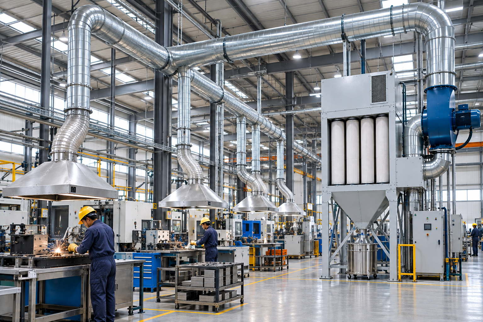
Industrial facilities generate heat, dust, fumes, mist, vapours, and other airborne contaminants that can affect production areas and equipment. A properly designed ventilation system helps control these conditions by moving air in a controlled manner and, where required, capturing contaminants at their source.
Effective industrial ventilation design is more than installing exhaust fans. It requires careful consideration of contaminant sources, airflow, capture methods, ductwork, filtration, pressure, and the layout of the manufacturing facility.
This guide explains the key principles behind factory ventilation systems, industrial airflow design, and effective manufacturing ventilation.
Key Takeaways
- Industrial ventilation should be designed around the processes and contaminants present in the facility.
- Source capture is important for concentrated emissions such as dust, welding fumes, and oil mist.
- Airflow requirements depend on the capture method, contaminant characteristics, and facility layout.
- Ductwork design directly affects system resistance and extraction performance.
- The blower must be selected based on both required airflow and total system pressure.
- General ventilation and local exhaust ventilation serve different purposes and may be used together.
- Maintenance and airflow monitoring are essential for long-term system performance.
What Is Industrial Ventilation Design?
Industrial ventilation design is the engineering process of controlling the movement of air within a manufacturing or industrial facility.
A ventilation system may be designed to:
- Remove airborne contaminants
- Control heat
- Provide fresh air
- Maintain desired pressure relationships
- Capture process emissions
- Reduce contaminant dispersion
- Support acceptable workplace conditions
A typical industrial ventilation system can include:
- Capture hoods or enclosures
- Ductwork
- Filtration equipment
- Exhaust or supply fans
- Dampers
- Air inlets
- Controls and monitoring equipment
The components must work together. Increasing the capacity of one component does not necessarily improve the performance of the entire system.
Local Exhaust vs General Ventilation
One of the first decisions in ventilation design is determining whether the application requires local exhaust, general ventilation, or a combination of both.
Local Exhaust Ventilation
Local exhaust ventilation captures contaminants close to their source.
Examples include:
- Welding fume extraction
- CNC mist collection
- Grinding dust extraction
- Powder handling extraction
- Process hoods
- Machine enclosures
The primary objective is to prevent contaminants from dispersing into the surrounding workspace.
General Ventilation
General ventilation manages air throughout the facility rather than capturing contaminants directly at their source.
It can be used for:
- Heat removal
- Fresh-air supply
- Dilution of residual contaminants
- Overall air movement
- Facility environmental control
General ventilation can complement local exhaust but should not automatically be considered a substitute for source capture.
The Basic Principle of Source Capture
For processes that generate concentrated emissions, the closer the contaminant is captured to its source, the less opportunity it has to disperse.
For example, consider a welding workstation.
An extraction arm positioned close to the welding operation can capture fumes before they spread through the surrounding workspace.
If the same fumes are allowed to disperse throughout a factory, considerably more air may need to be moved to achieve the same level of contaminant control.
This makes source capture an important principle in industrial airflow design.
Step 1: Identify the Contaminant Sources
The first stage of ventilation design is to identify where contaminants are generated.
Typical sources include:
- Welding stations
- Grinding machines
- CNC machining centers
- Cutting equipment
- Powder handling points
- Mixing operations
- Material transfer
- Painting and coating processes
- Heat-generating machinery
- Chemical processing equipment
Each source should be evaluated individually before determining the overall ventilation arrangement.
Step 2: Characterize the Contaminant
Different contaminants behave differently in an air stream.
Important characteristics include:
- Particle size
- Concentration
- Temperature
- Density
- Moisture
- Chemical properties
- Generation rate
- Combustibility
- Whether the contaminant is particulate, mist, vapour, or gas
For example, dry grinding dust requires a different collection approach from CNC oil mist.
Similarly, welding fumes require different filtration considerations from large, coarse particles.
Step 3: Select the Capture Method
The capture arrangement should match the process.
Common methods include:
Enclosures
The process is partially or completely enclosed to contain emissions.
Extraction Hoods
A hood is positioned over or near the emission source.
Flexible Extraction Arms
Flexible arms allow the operator to position the capture point close to the source.
Downdraft Tables
Air is drawn downward through a work surface to capture contaminants.
Side-Draft Hoods
Air is drawn horizontally across the process toward the extraction point.
Machine-Integrated Extraction
The extraction system is incorporated directly into the machine or enclosure.
The capture method has a major influence on the airflow required.
Step 4: Determine Airflow Requirements
Airflow is one of the most important aspects of industrial ventilation design.
The required airflow depends on:
- Hood geometry
- Distance from the contaminant source
- Capture method
- Source characteristics
- Number of extraction points
- Operating conditions
- Duct resistance
- Filter resistance
Simply selecting a high-CFM blower does not guarantee effective capture.
The airflow must be delivered where it is needed.
Step 5: Design the Ductwork
Ductwork transports contaminated air from the capture point to the filtration equipment.
Important design considerations include:
- Duct diameter
- Duct length
- Number of branches
- Elbows and bends
- Branch connections
- Air velocity
- Static pressure
- Leakage
- Material selection
Poor duct design can result in:
- Excessive pressure loss
- Inadequate airflow
- Dust settling
- High energy consumption
- Uneven extraction between branches
For dust collection systems, maintaining an appropriate transport velocity is particularly important to prevent material from settling inside the ductwork.
Step 6: Calculate System Static Pressure
The blower must overcome the resistance created by the entire ventilation system.
Sources of pressure loss can include:
- Capture hoods
- Ductwork
- Elbows
- Dampers
- Filters
- Silencers
- Exhaust outlets
- Other system components
The total system resistance should therefore be calculated before selecting the blower.
A blower rated for high airflow but insufficient pressure may fail to provide the required airflow once connected to the complete system.
Step 7: Select the Filtration System
When contaminated air is being extracted, the filtration technology should be selected according to the contaminant.
Examples include:
Dust
Dust collectors such as baghouse or cartridge systems.
Welding Fumes
Dedicated welding fume filtration systems.
Oil and Coolant Mist
Mist collectors designed for liquid aerosols.
Fine Particulate
Fine or high-efficiency filtration where required.
Vapours
Specialized filtration such as activated carbon may be appropriate for certain applications.
The filter should be selected based on the actual process rather than simply choosing the highest available filtration efficiency.
Step 8: Select the Blower
The blower must provide the required airflow at the calculated system resistance.
Two parameters are particularly important:
- Required airflow
- Required static pressure
The blower should also be evaluated for:
- Motor power
- Efficiency
- Operating point
- Noise
- Duty cycle
- Control requirements
For systems with variable production requirements, variable-frequency drives can sometimes be used to adjust fan speed according to operating conditions.
Centralized vs Individual Ventilation Systems
Manufacturing facilities can use individual extraction units, centralized systems, or a combination.
Individual Systems
A collector is installed directly at or near a machine.
Suitable applications can include:
- Individual CNC machines
- Welding stations
- Small workshops
- Portable operations
Advantages
- Simple installation
- Localized extraction
- Greater flexibility
- Minimal ductwork
Centralized Systems
Multiple machines or workstations are connected to a common filtration and extraction system.
Centralized systems can be useful for:
- Large manufacturing facilities
- Multiple fixed production lines
- Large numbers of extraction points
- Facilities with coordinated operating schedules
However, centralized systems require careful duct balancing and airflow management.
Air Balancing in Industrial Ventilation
When multiple extraction points are connected to a common system, airflow must be distributed appropriately.
If one branch offers significantly less resistance than another, it may draw more airflow.
This can result in:
- Excessive airflow at some locations
- Insufficient airflow at others
- Poor contaminant capture
- Increased energy consumption
Dampers and properly designed duct branches can help balance the system.
Make-Up Air
When large volumes of air are exhausted from a facility, replacement air must also be considered.
If a factory exhausts large quantities of air without adequate make-up air, it can create excessive negative pressure.
Potential consequences include:
- Difficulty opening doors
- Uncontrolled air infiltration
- Reduced exhaust performance
- Drafts
- Pressure-related operational problems
Therefore, factory ventilation systems should consider both exhaust and replacement air.
Natural vs Mechanical Ventilation
Natural Ventilation
Natural ventilation uses openings such as:
- Windows
- Louvers
- Roof vents
- Doors
- Building openings
Air movement is driven by wind and temperature differences.
Natural ventilation can support general facility air movement but is difficult to control precisely.
Mechanical Ventilation
Mechanical ventilation uses fans and engineered ductwork to control airflow.
It provides greater control over:
- Air volume
- Air direction
- Extraction points
- Filtration
- Pressure relationships
Mechanical systems are particularly useful when contaminant control needs to be predictable.
Designing Ventilation for Different Manufacturing Processes
Different processes require different ventilation approaches.
| Process | Typical Contaminant | Possible Ventilation Approach |
|---|---|---|
| Welding | Fumes | Source extraction |
| Grinding | Dust | Local dust extraction |
| CNC machining | Oil/coolant mist | Machine mist collection |
| Powder handling | Fine powder | Enclosure + extraction |
| Cutting | Dust/smoke | Local extraction |
| Heat-generating processes | Heat | General exhaust/supply |
| Chemical processes | Vapours/gases | Process-specific extraction |
| Assembly | Low-level residual emissions | General ventilation |
The final system should always be engineered around the actual process conditions.
Common Industrial Ventilation Design Mistakes
Designing Around the Fan Instead of the Process
Starting with a blower and trying to adapt the rest of the system around it can result in poor capture.
The process should be assessed first.
Using General Ventilation for Concentrated Emissions
Large exhaust fans may move significant amounts of air without capturing contaminants at their source.
Poor Hood Placement
A hood positioned too far from the source may require substantially more airflow to achieve effective capture.
Undersized Ductwork
Small ducts can increase pressure losses and affect airflow.
Excessive Bends
Unnecessary elbows and abrupt changes in direction can increase system resistance.
Ignoring Make-Up Air
Exhausting large quantities of air without considering replacement air can affect building pressure and system performance.
Failing to Consider Future Expansion
Adding machines later can change the airflow requirements of a centralized system.
Designing with reasonable expansion capacity can make future modifications easier.
Maintenance and Performance Monitoring
Even a well-designed ventilation system can lose performance over time.
Regular checks should include:
- Airflow
- Filter pressure drop
- Fan condition
- Motor condition
- Duct leakage
- Hood condition
- Damper position
- Filter condition
- Dust accumulation
- Extraction performance
Changes in airflow or pressure can provide early indications of problems such as filter loading, blocked ductwork, or mechanical issues.
How Powertech Approaches Industrial Ventilation
Powertech develops industrial pollution control solutions based on the process, contaminant, airflow requirement, and facility layout.
Depending on the application, a system may incorporate:
- DustBag industrial dust collectors
- MistKiller oil and coolant mist collectors
- FumeKiller welding fume extraction systems
- Local exhaust ventilation
- Centralized extraction
- Customized ductwork
- Industrial blowers
- Multi-stage filtration
The objective is to develop an extraction system in which the capture method, ductwork, filtration, and blower operate as a coordinated system.
Industrial ventilation design is the engineering of airflow, extraction, filtration, ductwork, and ventilation equipment to control contaminants, heat, and air movement within an industrial facility.
A typical system can include capture hoods or enclosures, ductwork, filtration equipment, blowers, dampers, air inlets, and monitoring or control equipment.
Local exhaust captures contaminants near their source, while general ventilation manages air throughout a larger area. They can be used together depending on the application.
Required airflow depends on the capture method, hood geometry, source characteristics, capture distance, number of extraction points, ductwork, filtration resistance, and operating conditions.
Ductwork transports air between the capture points and filtration equipment. Its diameter, length, fittings, branches, and airflow velocity influence system resistance and performance.
When large quantities of air are exhausted from a facility, replacement air may be required to prevent excessive negative pressure and maintain proper system performance.
Yes. Multiple machines can be connected to a centralized system when the airflow, ductwork, filtration capacity, blower, and system balancing are appropriately designed.
Inspection frequency depends on the application, operating conditions, contaminant loading, equipment design, and applicable requirements. Airflow, filters, ductwork, fans, and capture points should be monitored regularly.
Effective industrial ventilation design begins with understanding the manufacturing process rather than simply selecting fans or filtration equipment. The contaminant source, capture method, airflow, ductwork, filtration, blower, and make-up air all influence the performance of the finished system. For concentrated emissions such as welding fumes, grinding dust, oil mist, and powder, source capture can prevent contaminants from dispersing into the production environment. General factory ventilation systems can then support overall air movement, heat management, and residual contaminant control. A properly engineered industrial airflow design treats the extraction system as a complete network. When capture, ductwork, filtration, blower capacity, balancing, and maintenance are considered together, manufacturers can achieve more consistent and reliable manufacturing ventilation performance.