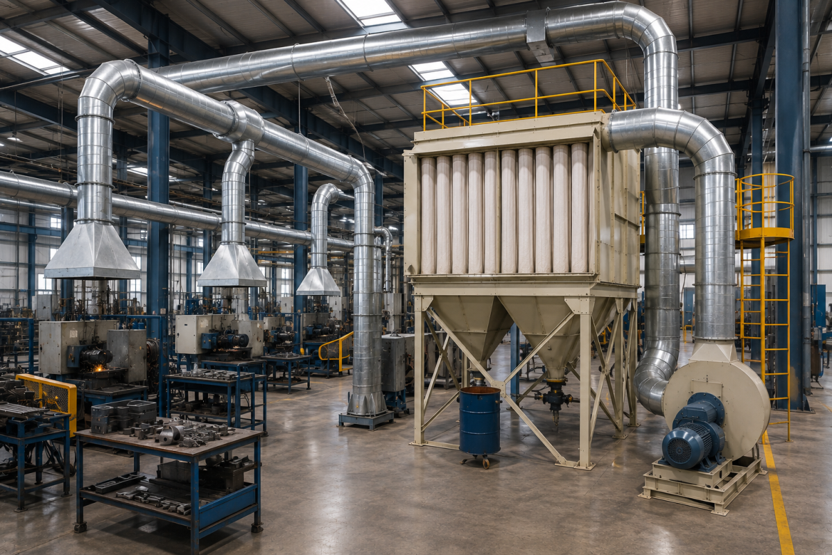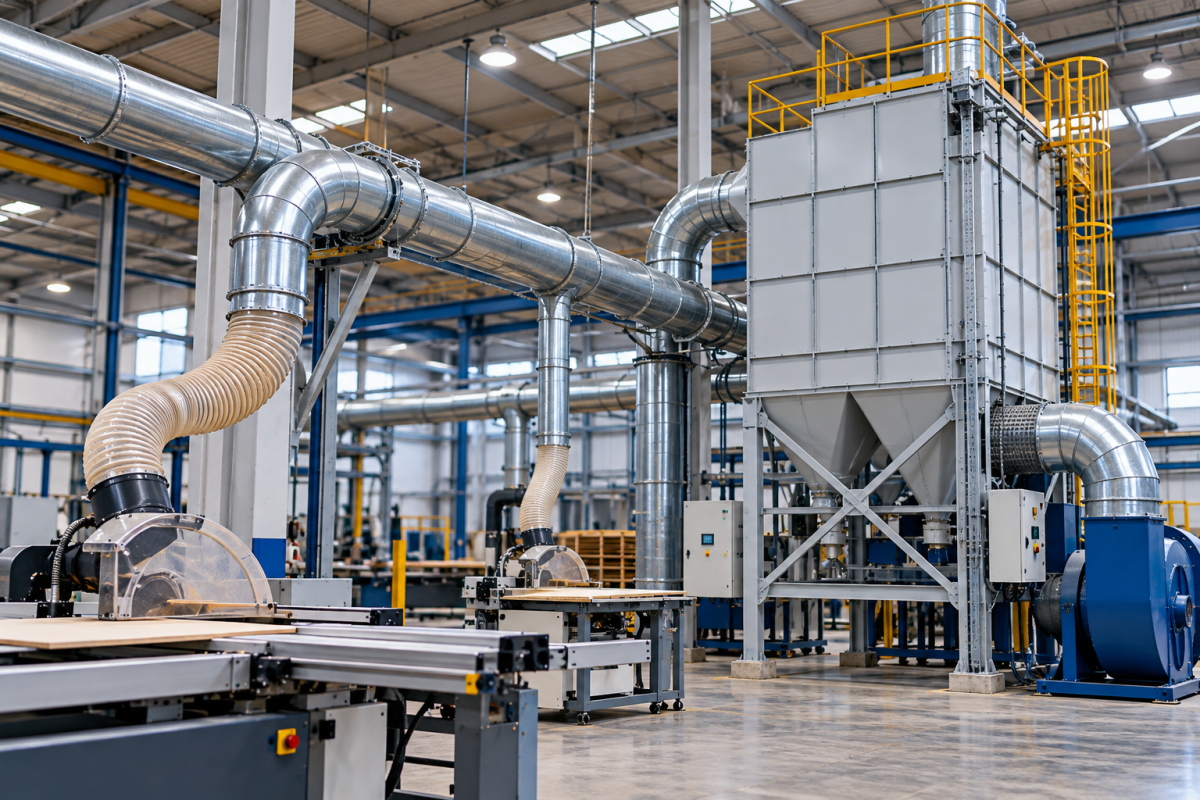
Choosing the right industrial dust collector is not just about selecting a unit with a high filtration efficiency. The system must also move enough air to capture dust at the source, transport it through the ductwork, and maintain effective collection under actual operating conditions.
This is where dust collector airflow becomes a critical design consideration. Too little airflow can allow dust to escape into the workplace or settle inside ductwork. Excessive airflow, on the other hand, can increase energy consumption, operating costs, and filter loading without necessarily improving dust capture.
For industrial facilities, determining the right airflow requires an understanding of the dust-generating process, extraction hood design, duct dimensions, conveying velocity, and the resistance created by filters and other system components.
This guide explains how to calculate dust collector CFM requirements, estimate the airflow needed for different industrial applications, and avoid common sizing mistakes.
What Is Dust Collector Airflow?
Dust collector airflow is the volume of air moved through a dust collection system over a specified period. It is commonly expressed in cubic feet per minute (CFM) or cubic metres per hour (m³/hr).
Airflow determines how much contaminated air the system can draw through its capture points. However, the required airflow depends on the application rather than on the collector alone.
For example, a small sanding station may require a different airflow arrangement from a grinding machine, a woodworking process, or a production line handling fine powder.
Three related factors must be considered when designing a dust collection system:
- Capture airflow: The airflow needed to draw dust into the hood or extraction point before it spreads into the workplace.
- Duct conveying velocity: The air velocity required to transport collected dust through the ductwork without excessive settling or accumulation.
- Collector operating airflow: The airflow the fan must deliver through the complete system, accounting for ductwork, filters, hoods, and other resistance.
These factors are related, but they are not interchangeable. A dust collector with a high advertised airflow may still provide insufficient capture at a poorly designed extraction hood.
What Is CFM in Dust Collection?
CFM stands for cubic feet per minute. It measures the volume of air moving through a dust extraction system every minute.
The term dust collector CFM is often used when comparing industrial dust collectors, but the number must be interpreted in the context of the system’s operating conditions.
A collector rated for a particular maximum CFM may deliver less airflow when connected to ductwork and filters that create resistance. Filter loading can also increase pressure drop and affect the airflow available at the extraction points.
CFM can be converted to cubic metres per hour using the following relationship:
1 CFM ≈ 1.699 m³/hr
For example:
| Airflow (CFM) | Approximate airflow (m³/hr) |
|---|---|
| 250 | 425 |
| 500 | 850 |
| 1,000 | 1,699 |
| 1,500 | 2,549 |
| 2,000 | 3,398 |
| 3,000 | 5,097 |
These figures are unit conversions, not recommended airflow values for specific industrial applications. Actual requirements must be calculated from the process and system design.
Why Is Correct Dust Collection Airflow Important?
Correct dust collection airflow affects both the performance and operating cost of an industrial dust extraction system.
1. Effective Dust Capture
Dust generated during grinding, cutting, polishing, sanding, and material handling can disperse quickly. The extraction hood must draw contaminated air into the system before the dust escapes into the surrounding area.
If airflow is insufficient for the hood geometry and source conditions, visible dust may escape even when the collector’s filters are suitable for the application.
2. Reliable Dust Transport Through Ductwork
Once dust enters the extraction system, the airflow must transport it through the ducts to the collector.
If conveying velocity is too low for the dust being handled, material may settle in horizontal ducts or accumulate at bends and branches. The appropriate velocity depends on particle characteristics, material loading, moisture content, and duct configuration.
3. Consistent System Performance
In a multi-point dust collection system, each extraction point needs an appropriate share of the available airflow. Poorly balanced ductwork can cause some machines to receive adequate extraction while others perform poorly.
A correctly designed system considers the operating requirements of individual branches as well as the total airflow required by the collector.
4. Energy and Operating Costs
Moving air requires energy. Oversizing the fan or operating at unnecessarily high airflow can increase power consumption, noise, and operating costs.
The objective is not to maximize CFM. It is to deliver the airflow required for effective capture and transport at the pressure conditions of the system.
How to Calculate Dust Collector CFM Requirements
The airflow calculation depends on whether you are sizing a single extraction point or an entire industrial dust collection system.
Step 1: Determine the Airflow Required at Each Extraction Point
For each machine or process, identify the capture arrangement and the airflow needed to control dust generation.
Relevant factors include:
- The type and intensity of the dust-generating operation.
- The size and geometry of the extraction hood.
- The distance between the hood and the dust source.
- Whether the process is enclosed or open.
- The direction and speed of dust generation.
- The number of extraction points connected to the system.
For an enclosed machine, airflow may be determined by the enclosure openings and the required inward air movement. For an open grinding or polishing operation, hood geometry and source-capture requirements become particularly important.
Avoid assigning the same CFM to every machine simply because the machines are located in the same factory.
Step 2: Add the Airflow Requirements of Simultaneously Operating Points
For a system serving several extraction points, the initial total airflow requirement can be estimated by adding the airflow required at each point expected to operate simultaneously.
The basic relationship is:
Total airflow = Sum of the required airflow at simultaneously operating extraction points
For example, suppose a system serves four machines, each requiring an illustrative 500 CFM at its extraction point.
If all four machines operate simultaneously, the combined nominal requirement is 2,000 CFM.
If only two machines are intended to operate at a time, the operating demand may be lower, but this should only be used when the operating controls and production procedures reliably prevent additional branches from opening.
This calculation establishes an initial airflow requirement. It does not complete the system design.
Step 3: Check Duct Conveying Velocity
The ductwork must transport the dust without unacceptable accumulation.
For a round duct, the relationship between airflow, duct area, and air velocity is:
[
Q = V x A
]
Where:
- (Q) is volumetric airflow.
- (V) is average air velocity.
- (A) is the duct’s internal cross-sectional area.
When airflow is expressed in cubic feet per minute and velocity in feet per minute, the area is expressed in square feet.
The equation can be rearranged to estimate the airflow needed for a chosen duct velocity:
[
CFM = Velocity (ft/min) x Area (ft}^2
]
For example, a 6-inch-diameter round duct has an internal area of approximately 0.196 square feet. At an illustrative air velocity of 4,000 ft/min, the corresponding airflow is approximately 785 CFM.
This is a mathematical example, not a universal design recommendation. The appropriate conveying velocity must be selected for the material being transported and the system’s operating conditions.
Step 4: Calculate System Static Pressure
After establishing the airflow requirements, determine the resistance the fan must overcome.
Static pressure losses can arise from:
- Extraction hoods and inlet openings.
- Straight duct sections.
- Bends, elbows, and branch connections.
- Dampers and other fittings.
- Filter media.
- Collector inlets and outlets.
- Exhaust ductwork, where applicable.
The fan must deliver the required airflow at the calculated operating static pressure. Selecting a fan using only its maximum or free-air CFM rating can result in inadequate airflow after installation.
For multi-point systems, the design should evaluate the most demanding airflow path and ensure that each branch receives its required flow.
Step 5: Account for Filter Loading and Operating Conditions
As dust accumulates on filter media, the pressure drop across the filters may increase. The fan and filtration system must be suitable for the expected operating range.
Designers should establish the airflow and pressure conditions at which the system is expected to operate, along with the criteria for filter cleaning or replacement.
A system that meets its airflow requirement with clean filters but cannot maintain adequate extraction as filters load may not be suitable for continuous industrial production.
Typical Dust Collector Airflow Requirements by Application
Airflow requirements vary considerably with machine design, dust generation rate, hood geometry, enclosure, and operating conditions. The following table provides qualitative guidance rather than fixed CFM recommendations.
| Industrial application | Main airflow consideration |
|---|---|
| Grinding machines | Hood position, wheel size, dust trajectory, and enclosure |
| Polishing and buffing | Capture arrangement around the workpiece and wheel |
| Cutting operations | Dust generation rate, enclosure, and cutting method |
| Sanding | Hood design, surface area, and the rate of dust generation |
| Deburring | Workpiece geometry and the location of dust release |
| CNC machining | Process enclosure and the characteristics of generated particulate matter |
| Powder handling | Material properties, transfer-point enclosure, and containment |
| Foundry operations | Process-specific emissions, thermal conditions, and capture arrangements |
| Multiple fabrication machines | Combined airflow demand, branch balancing, and simultaneous usage |
These applications should not be sized using a single generic CFM value. The required airflow must be determined from the machine manufacturer’s recommendations, accepted engineering guidance, and the actual extraction arrangement.
For example, a grinding machine with a well-designed enclosure may need a different airflow from an open grinding station performing a similar operation. The machine layout and capture method can materially affect the requirement.
Dust Collector Airflow vs. Duct Air Velocity
Airflow and air velocity are often confused, but they describe different properties.
Airflow is the volume of air moving through the system per unit of time.
Air velocity is the speed at which the air moves through a duct or opening.
A larger duct can carry the same airflow at a lower velocity than a smaller duct. This is why duct diameter must be considered alongside CFM when designing dust collection airflow.
If the duct is too large for the selected airflow, conveying velocity may be inadequate for the dust being transported. If the duct is too small, resistance may increase substantially, raising fan requirements and potentially reducing the airflow available at the extraction hood.
The correct duct size is therefore determined by balancing required airflow, material-appropriate conveying velocity, pressure losses, and practical installation constraints.
How to Size Airflow for a Centralized Dust Collection System
Centralized dust collection systems connect several machines or extraction points to a common filtration unit.
Sizing these systems requires more than adding up the maximum airflow ratings of all connected machines. The design must establish which branches operate together, the airflow required at each branch, and how the duct network distributes air.
A sound design process typically includes the following:
- Map every extraction point. Record the machines, hood types, duct connections, and operating requirements.
- Establish simultaneous demand. Determine which machines can operate at the same time and whether operating controls reliably manage that demand.
- Design the duct network. Select duct dimensions and branch configurations to deliver the required airflow while maintaining suitable conveying velocity.
- Calculate pressure losses. Account for the most demanding airflow path through the ductwork, fittings, and filtration equipment.
- Select the fan and collector. Confirm that the equipment can deliver the required airflow at the calculated operating pressure.
- Provide for balancing and verification. Include suitable provisions for adjusting and measuring airflow at individual branches.
Airflow controls can help manage systems with variable demand, but they must be designed around the actual operating requirements. Simply closing unused branches or reducing fan speed without verification can compromise capture at active stations.
How Filter Type Affects Dust Extraction Airflow
The filtration system influences the resistance the fan must overcome, making filter selection an important part of airflow design.
Non-Woven Polyester Filters
Non-woven polyester filter media can be used in suitable industrial dust collection applications, depending on the particle characteristics and operating conditions.
Powertech’s DustBag industrial dust collector is designed for industrial dust extraction applications. Its suitability for a particular process should be assessed against the dust type, required airflow, filtration specifications, and operating conditions.
Reverse-Pulsed-Jet Filtration
Reverse-pulsed-jet systems use compressed-air pulses to dislodge accumulated dust from compatible filter elements. This cleaning arrangement can support continuous operation in applications where dust loading and filter characteristics are appropriate.
The cleaning system does not eliminate the need to size the fan and filtration equipment correctly. Airflow, pressure drop, dust properties, and cleaning requirements must all be considered when selecting the collector.
Why Filter Selection Matters
The appropriate filter depends on particle characteristics, dust loading, temperature, moisture, chemical compatibility, and the required collection performance.
A filter’s nominal efficiency alone does not establish the overall performance of the system. Capture effectiveness, filter sealing, operating airflow, maintenance, and the properties of the dust also matter.
Where dust presents a combustible, toxic, or otherwise hazardous risk, the system may require additional engineering controls and a specialized risk assessment.
Common Mistakes When Calculating Dust Collector CFM
1. Selecting a Collector Based Only on Maximum CFM
A maximum airflow rating may not represent the airflow available after connecting the ductwork and filters. Always evaluate the fan’s performance at the expected operating static pressure.
2. Ignoring Hood Design
A large collector cannot compensate for a poorly positioned or badly designed extraction hood. Dust may escape before it reaches the system, regardless of the filter’s efficiency.
3. Using the Same Airflow for Every Machine
Grinding, polishing, powder handling, and enclosed machining operations have different capture and transport requirements. Airflow should be based on the application.
4. Overlooking Duct Velocity
The system must maintain appropriate velocity for the dust being transported. Insufficient conveying velocity may lead to accumulation, while excessive velocity can increase pressure losses and wear.
5. Ignoring Filter Loading
Airflow should be evaluated under realistic operating conditions, including the expected pressure drop across the filters.
6. Oversizing the System Without Engineering Justification
Excessive airflow can increase fan energy consumption and operating costs. A correctly sized system delivers the airflow needed for effective capture and transport without unnecessary capacity.
7. Failing to Verify Installed Performance
After installation, airflow should be measured and adjusted as needed. Verification helps confirm that the system delivers the intended performance at the actual extraction points.
Practical Dust Collector Airflow Calculation Checklist
Before selecting an industrial dust collector, establish the following information:
- Dust-generating processes and materials identified.
- Extraction hood and enclosure requirements documented.
- Required airflow at each capture point established.
- Simultaneously operating machines identified.
- Duct diameters and material-appropriate conveying velocities determined.
- Pressure losses across ducts, fittings, and filters calculated.
- Fan performance checked at the required operating static pressure.
- Filter specifications and expected loading considered.
- Maintenance and filter-cleaning arrangements defined.
- Airflow measurement and commissioning requirements established.
These details provide a stronger basis for selecting a collector than comparing equipment by CFM alone.
Conclusion
Determining the right dust collector airflow requires a system-level approach. CFM establishes how much air must move through the system, but effective dust collection also depends on capture hood design, duct velocity, static pressure, filtration, and operating conditions.
For a single machine, the airflow requirement should be established at the extraction point. For a centralized installation, the design must also account for simultaneous demand, duct network resistance, and airflow distribution across all connected branches.
Powertech Pollution Controls provides industrial dust collection solutions for manufacturing and material-processing applications. When evaluating a suitable system, share the dust-generating process, number of extraction points, operating schedule, layout, and available technical specifications so that the airflow and filtration requirements can be assessed.
The goal is not simply to purchase a dust collector with a high CFM rating. It is to design a system that delivers the required airflow where it is needed and maintains effective performance under real operating conditions.