
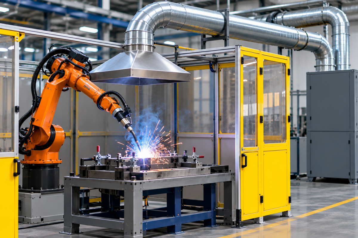
Robotic welding has transformed modern manufacturing by improving production speed, repeatability, and consistency. Automated welding cells are widely used in automotive manufacturing, heavy fabrication, sheet metal processing, machinery production, and other industrial applications where high-volume welding is required.
However, automation does not eliminate the fumes generated during welding. In many cases, robotic welding creates a concentrated and continuous source of airborne contaminants because the process operates repeatedly within an enclosed or partially enclosed workspace.
This makes robotic welding fume extraction an important part of automated cell design. An effective system must capture fumes close to their point of generation without interfering with robot movement, welding performance, operator access, or production efficiency.
Unlike conventional welding stations, automated cells require extraction systems designed around robot paths, welding fixtures, enclosure geometry, ventilation openings, and production cycles. Simply installing an extraction hood above a robot may not provide adequate capture throughout the entire welding sequence.
This guide explains how to approach fume extraction for robotic welding cells, the available capture arrangements, key system design considerations, and how manufacturers can select an appropriate extraction solution.
Why Robotic Welding Cells Need Dedicated Fume Extraction
Welding fumes are generated when the intense heat of the welding process vaporises metals and other materials. These vapours cool and condense into fine airborne particles. Depending on the welding process, base material, filler metal, and consumables, the fumes may contain substances such as iron, manganese, chromium, nickel, and other metal compounds.
The composition and potential health risks vary with the materials and welding parameters involved.
In automated welding, several characteristics make effective extraction particularly important.
1. Continuous and Repetitive Fume Generation
A robotic welding system may perform hundreds or thousands of welds during a production shift. Even if individual welding cycles are relatively short, repeated operation can generate a substantial cumulative fume load.
Unlike a manual welding station where an operator may pause between tasks or move between locations, a robotic cell can repeat the same process for extended periods.
Extraction must therefore be designed for the actual production duty cycle, including simultaneous welding operations and the number of robots working within the cell.
2. Multiple Fume Generation Points
A robotic welding cell may contain several welding positions, fixtures, and components. Depending on the robot’s programmed movement, the welding arc can operate at different locations within the enclosure.
This means the source of fume generation is not necessarily fixed.
An extraction arrangement designed around a single welding position may struggle to capture fumes effectively when the robot moves to another fixture or works on a different section of the component.
3. Enclosed and Partially Enclosed Workspaces
Robotic welding cells commonly use safety enclosures, protective screens, curtains, and access doors. These structures help protect personnel from welding arcs and moving equipment, but they also influence airflow.
Poorly planned ventilation can allow fumes to accumulate inside the enclosure. When access doors open or the cell is unloaded, accumulated fumes may escape into surrounding production areas.
A properly designed robotic welding ventilation system must account for both the internal airflow pattern and the way contaminated air is removed from the cell.
4. Limited Operator Access During Production
Because robotic welding is automated, operators generally do not remain beside the welding arc during the production cycle. However, personnel may enter the cell for loading, unloading, fixture adjustment, maintenance, and inspection.
Extraction should continue to manage residual fumes appropriately, including during relevant access and unloading procedures. The system should not be designed solely around the period when the robot is actively welding.
How Robotic Welding Fume Extraction Works
A robotic welding fume extraction system typically consists of four main elements:
- Capture arrangement: Hoods, extraction openings, or enclosure connections collect contaminated air.
- Duct network: Ductwork transports the extracted air to the filtration equipment.
- Fume filtration unit: The extraction unit removes airborne contaminants using filtration stages selected for the application.
- Fan and discharge arrangement: The fan maintains the airflow required to overcome resistance through the capture points, ductwork, and filters.
The extraction arrangement must maintain suitable airflow at the actual fume capture locations. Its performance depends on the complete system, not simply the rated capacity of the extraction unit.
The fundamental engineering principles are similar to those used in other industrial welding applications. Powertech’s welding fume extractor guide explains how source capture, filtration, airflow, and system configuration work together across different welding applications.
The design should also consider whether extracted air is discharged outside the building or returned after treatment. Any recirculation arrangement requires appropriate assessment of the contaminants, filtration performance, applicable regulations, and workplace requirements.
Common Fume Capture Methods for Robotic Welding
There is no single capture arrangement suitable for every automated welding cell. The appropriate method depends on cell size, welding process, robot movement, enclosure design, and the number of active welding positions.
1. Enclosure-Based Extraction
Enclosure-based extraction removes contaminated air directly from a robotic welding enclosure.
Extraction openings are positioned at suitable locations within the enclosure to establish an airflow pattern that draws fumes away from the welding area and towards the extraction duct.
This approach is particularly useful when:
- The welding process takes place within a defined enclosure.
- The robot operates across multiple positions inside the cell.
- The enclosure can be designed with controlled air inlets and extraction outlets.
- A consistent airflow pattern can be maintained throughout the production cycle.
The location of extraction openings is important. If the airflow is poorly distributed, fumes may remain trapped in certain sections of the cell or escape through access openings.
The design must also avoid excessive air velocities that could disturb the welding shielding gas or affect the welding process.
2. Canopy or Overhead Extraction
An overhead extraction hood can be installed above the robotic welding area to collect rising fumes.
This arrangement uses the natural upward movement of heated welding fumes, combined with mechanical extraction, to remove contaminants from the cell.
Canopy extraction may be considered when:
- The welding area is relatively compact.
- The cell geometry allows fumes to rise towards the capture point.
- Robot movement does not create significant interference with the hood.
- The extraction arrangement can prevent fumes from spreading into surrounding work areas.
However, an overhead canopy is not always sufficient on its own. Fumes may disperse before reaching the hood, especially in large cells or areas with strong cross-draughts.
Where practical, capturing fumes closer to their source or controlling the enclosure airflow can provide a more reliable approach.
3. Integrated Extraction Through Fixtures or Tooling
Some automated welding applications can incorporate extraction openings into the fixture, welding table, or dedicated tooling.
This can bring the capture point closer to the welding operation and reduce the distance fumes travel before being collected.
Integrated extraction may be useful where:
- Welding takes place repeatedly at predictable positions.
- The component or fixture geometry supports localised capture.
- The extraction arrangement can be designed without obstructing clamping or robot access.
- The process permits suitable airflow without affecting shielding gas protection.
This approach requires close coordination between the welding automation team and the ventilation system designer.
4. Combination Capture Systems
Large robotic welding cells may require more than one extraction method.
For example, an enclosure-based extraction system may be combined with local extraction near specific welding fixtures. This can help address different fume generation locations while maintaining a controlled airflow pattern.
The final arrangement should be based on the cell’s actual operating conditions rather than adding capture points without evaluating their combined airflow requirements.
Key Design Considerations for Automated Welding Extraction
Selecting a suitable extraction arrangement requires more than estimating the volume of fumes generated. The system must work with the robot’s operating envelope, enclosure design, welding process, and production schedule.
1. Robot Movement and Working Envelope
Robotic arms move through programmed paths that may cover a large area within the cell. Extraction hoods, duct connections, and flexible components must not obstruct these movements.
During system design, consider:
- The robot’s full range of movement, including its maximum reach.
- The location of welding fixtures and component loading points.
- The position of cables, torches, and other automation equipment.
- Potential collisions between the robot, extraction components, and workpieces.
- Access required for maintenance and fixture changes.
Fixed extraction openings are often preferable where the cell layout allows them. Flexible extraction components may be considered in specific applications, but they must be protected against mechanical damage and interference.
For applications using movable capture points, Powertech’s adjustable fume extraction arm provides a flexible hood-positioning arrangement. Whether an extraction arm is appropriate for a robotic cell depends on the robot’s movement, mounting position, reach, and the protection required against mechanical interference.
2. Welding Process and Materials
The extraction requirements can vary considerably depending on the welding process.
| Welding process | Extraction considerations |
|---|---|
| Robotic MIG/MAG welding | Continuous fume generation, wire feed, shielding gas, and repeated weld cycles |
| Robotic TIG welding | Fume generation varies with materials and parameters; capture remains necessary where contaminants are produced |
| Robotic spot welding | Fume generation at repeated contact points and potential emissions from coatings or surface contaminants |
| Robotic laser welding | Process-specific airborne emissions and the need for suitable enclosure and extraction design |
The material being welded also matters. Stainless steel, galvanised steel, coated components, and aluminium alloys can produce different airborne contaminants.
For example, welding stainless steel can generate fumes containing chromium and nickel compounds. Welding galvanised components may produce zinc-containing fumes. Surface coatings, oils, paints, and cleaning residues can further affect the emission profile.
A suitable extraction and filtration system should therefore be selected after reviewing the base materials, filler metals, coatings, and welding parameters.
3. Airflow and Extraction Capacity
Airflow is one of the most important parameters in robotic welding fume extraction.
The required airflow depends on the capture method, enclosure volume, opening areas, number of active welding points, and the airflow pattern needed to control emissions.
For enclosure-based extraction, the design should establish an appropriate inward airflow through the intended openings while preventing fumes from escaping.
For local capture arrangements, the required airflow depends on the hood geometry, distance from the welding source, and the ability to capture fumes without disturbing the process.
A system should not be selected solely on the basis of the fan’s maximum airflow rating. The actual airflow delivered at each capture point must account for resistance from:
- Duct length and diameter.
- Elbows, bends, and branch connections.
- Dampers and balancing devices.
- Filters and their operating condition.
- Inlet and outlet arrangements.
Where multiple robotic cells are connected to one central system, the designer must also establish how many cells operate simultaneously and whether the duct network can maintain the required airflow under those conditions.
4. Static Pressure and Duct Network Design
In a centralized automated welding extraction system, duct design has a direct influence on performance.
Static pressure represents the resistance the fan must overcome to move air through the system. Undersized ductwork, excessive bends, poorly designed branches, and restrictive filters can increase pressure losses.
The duct network should be designed to:
- Maintain the required airflow at each extraction point.
- Minimise unnecessary pressure losses.
- Allow appropriate balancing between branches.
- Provide access for inspection and cleaning.
- Avoid interference with robot movement and material handling.
- Accommodate planned production expansion where practical.
For multiple robotic cells, branch dampers or other airflow control arrangements may be required. These should be selected and commissioned as part of the overall system rather than treated as an afterthought.
5. Filtration Technology
Robotic welding fume filtration equipment must be suitable for the particle characteristics and contaminants generated by the welding process.
Powertech’s Fumekiller® uses electrostatic filtration and is positioned for welding fume applications. Its Fumekiller® product information describes the collection technology and available system features.
A filtration arrangement may include electrostatic collection or other suitable filtration stages, depending on the application. The final selection should consider:
- Filter efficiency for the relevant particle sizes.
- Filter media or collection-cell compatibility with the welding fume.
- Dust loading and expected operating hours.
- Cleaning mechanism and compressed-air requirements, where applicable.
- Differential-pressure or other condition monitoring.
- Filter replacement or collection-cell cleaning access.
- Any additional treatment required for the contaminant profile.
Where combustible metal dust or other special hazards may be present, the system requires a separate hazard assessment and suitable engineering safeguards. Standard welding fume collectors should not automatically be assumed suitable for every metal or process.
6. Shielding Gas and Welding Quality
One of the most important design considerations in automated welding is avoiding interference with shielding gas.
MIG/MAG and TIG welding commonly use shielding gases to protect the weld pool from atmospheric contamination. Excessive air movement around the welding arc can disturb this protection and contribute to weld defects.
Extraction should therefore capture fumes without creating disruptive cross-draughts around the torch and weld area.
The ventilation designer should coordinate with the welding automation team to verify that the extraction arrangement does not compromise weld quality, robot cycle performance, or process repeatability.
7. Integration With Production and Safety Systems
An automated welding cell may have interlocks, access doors, sensors, robot controllers, and production management systems.
The extraction system should be considered during the automation design stage so that its operation can be coordinated with the cell.
Depending on the risk assessment and control philosophy, this may include:
- Starting extraction before welding begins.
- Maintaining extraction during the welding cycle.
- Allowing an appropriate clearance period after welding stops.
- Providing airflow or filter-condition alarms.
- Monitoring the operating status of the extraction unit.
- Defining procedures for extraction failure or maintenance.
The exact control logic should be established by the project engineering team. Extraction should not be assumed to be effective merely because the fan is running.
Centralized vs Individual Extraction for Robotic Welding Cells
Manufacturers with several automated welding cells must decide whether each cell should have a dedicated extraction unit or whether multiple cells should connect to a centralized system.
Both arrangements can be suitable, depending on production requirements.
| Factor | Individual extraction units | Centralized extraction system |
|---|---|---|
| Installation | Dedicated unit for each cell | Shared filtration and fan equipment with duct branches |
| Layout | Suitable for independent or separated cells | Useful where cells can be connected through a coordinated duct network |
| Maintenance | Units are serviced individually | Main filtration equipment is serviced centrally |
| Airflow control | Managed for each cell | Requires branch balancing and system-level control |
| Expansion | Additional units can be installed | Expansion depends on spare fan, filter, and duct capacity |
| Equipment footprint | Multiple units may occupy floor space | Main equipment can be located in a common service area |
| Downtime | A fault may affect one cell | A central-unit fault may affect several connected cells |
| Investment | Can suit smaller or phased installations | May suit larger projects, depending on ductwork and operating requirements |
A centralized system may be attractive where multiple cells operate on a fixed production layout. Individual systems may be preferable where cells are separated, independently operated, or frequently relocated.
Some facilities may benefit from a combination of both arrangements.
The Powertech welding fume extraction pillar guide provides further guidance on choosing between portable, fixed, and centralized extraction configurations for different welding environments.
Common Mistakes in Robotic Welding Fume Extraction
Even a high-capacity extraction unit can perform poorly when the capture arrangement and system layout are not designed correctly.
Relying Only on an Overhead Hood
A hood installed above the welding robot may appear to be a simple solution, but it may not capture fumes effectively across the entire working envelope.
Fumes can disperse before reaching the hood, particularly when the robot welds at lower positions or when cross-draughts affect the airflow.
The capture arrangement should be assessed at different robot positions and operating conditions.
Ignoring Enclosure Openings
Access doors, loading openings, and material transfer points influence airflow through the cell.
If the system is designed without considering these openings, fumes may escape into the surrounding workshop.
Selecting Equipment Only by Airflow Rating
A high airflow figure does not guarantee effective fume capture. The fan must deliver the required airflow against the actual system resistance, and the capture points must be positioned correctly.
Overlooking Simultaneous Operation
A centralized system designed around one active welding cell may not provide sufficient capacity when several cells operate together.
The design should use realistic production schedules and simultaneous operating requirements.
Neglecting Filter Maintenance
As filters collect welding fume particles, pressure drop can increase and airflow may decline if the system is not maintained correctly.
Differential-pressure monitoring, planned inspections, and appropriate filter servicing help maintain system performance.
Designing Extraction After Automation Installation
Retrofitting extraction after robot placement can create challenges with duct routing, access, and interference with equipment.
Including extraction requirements during the initial cell design generally provides more opportunities to coordinate the ventilation system with the automation layout.
How to Select a Robotic Welding Fume Extraction System
Before specifying equipment, manufacturers should collect information about the welding process and the operating environment.
A practical assessment should include:
- Number of robotic cells: Identify how many cells require extraction and whether they operate simultaneously.
- Welding processes: Establish whether the application uses MIG/MAG, TIG, spot welding, laser welding, or another process.
- Materials and consumables: Document base metals, filler materials, coatings, and surface contaminants.
- Cell dimensions: Record enclosure size, access openings, fixtures, and robot working envelopes.
- Capture method: Evaluate enclosure extraction, overhead hoods, fixture extraction, or a combination.
- Airflow requirements: Calculate the airflow needed at each capture point under actual operating conditions.
- Ductwork: Assess routing, static pressure, balancing, and maintenance access.
- Filtration: Select filter media and treatment stages appropriate to the contaminants.
- Controls: Define operating sequences, alarms, interlocks, and fault procedures.
- Future production: Consider additional cells, longer operating hours, and possible changes to the welding process.
A site assessment and engineering review should confirm the final configuration before equipment is specified.
Why Source Capture Matters in Automated Welding
General workshop ventilation can help manage background airborne contaminants, but it should not be treated as a substitute for effective source capture where welding fumes are generated.
Source capture removes contaminated air close to the welding process before it spreads through the workplace. This can reduce the amount of fume that escapes into the surrounding environment and the burden placed on general ventilation.
For robotic welding, this is particularly relevant because the process can operate repeatedly within a defined area, making it possible to design extraction around the cell geometry and production cycle.
Powertech’s industrial air pollution control solutions explain how source capture, enclosure design, airflow, and filtration fit into a wider industrial air quality strategy.
For further technical guidance, the NIOSH engineering control guidance for welding fume extraction guns and the UK Health and Safety Executive’s guidance on reducing welding fume exposure explain important principles of exposure control.
Robotic welding fume extraction is the process of capturing and filtering airborne fumes generated during automated welding operations. It may use enclosure extraction, overhead hoods, fixture-based capture, or a combination of methods.
Not necessarily. A robotic cell can use a dedicated extraction unit or connect to a centralized system serving multiple cells. The appropriate arrangement depends on the number of cells, their operating schedules, airflow requirements, layout, and maintenance strategy.
Yes. A centralized system can serve multiple cells if its fan, filtration capacity, duct network, and control arrangement are designed for the expected simultaneous demand.
It can be suitable in some applications, but it is not automatically sufficient. The hood must capture fumes effectively across the welding area and operating positions. Enclosure-based or fixture-integrated extraction may be more appropriate in other applications.
The appropriate filtration technology depends on the welding process, materials, contaminant profile, and discharge requirements. Powertech positions Fumekiller® electrostatic filtration for welding fume applications. The final system configuration should be selected after assessing the actual application.
Yes, if the airflow is poorly designed. Excessive cross-draughts can disturb shielding gas and affect weld quality. The extraction arrangement should be coordinated with the welding process and validated during commissioning.
Robotic welding improves manufacturing productivity, but automation does not remove the need to control welding fumes. Repetitive welding cycles, multiple fume generation points, enclosed workspaces, and complex robot movements make extraction design an important part of automated cell planning. An effective robotic welding fume extraction system must account for the robot’s working envelope, welding process, materials, enclosure geometry, airflow, duct resistance, filtration, and production schedule. For facilities operating multiple automated cells, centralized extraction may offer a coordinated solution, while individual or hybrid arrangements may be more suitable for other layouts. The most important consideration is effective source capture under actual production conditions. Planning extraction alongside the robotic welding system helps manufacturers create a cleaner, better-controlled working environment without compromising welding quality or production efficiency. Powertech Pollution Controls provides industrial fume extraction solutions for manufacturing applications. A review of the welding process, cell layout, operating schedule, and extraction requirements can help determine the appropriate system configuration. Explore the welding fume extraction solutions from Powertech or Fumekiller® fume extraction systems for more information.