Capture Velocity Requirements for Welding Fume Extraction

Introduction

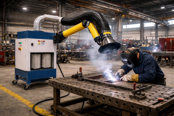
Effective welding fume control depends fundamentally on the ability to capture contaminants at the point of generation. In welding operations, fumes are produced at high temperatures and disperse rapidly into the surrounding air. If not captured immediately, they spread across the workspace, reducing air quality and increasing operator exposure.

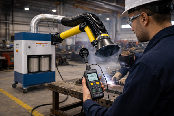
The key parameter that determines whether fumes are successfully captured is capture velocity welding fumes. Capture velocity defines the air speed required at the source to overcome the momentum of rising fumes and draw them into the extraction system.

In industrial environments, improper understanding of welding ventilation design often leads to inadequate airflow, resulting in poor system performance. A well-engineered approach to fume extraction airflow requirements ensures that contaminants are effectively removed before dispersion.

With over 30 years of experience, Powertech has designed industrial welding ventilation systems where optimizing capture velocity has significantly improved air quality and system efficiency across fabrication and manufacturing facilities.

Key Takeaways

  1. Capture velocity welding fumes is critical for effective source capture.
  2. Incorrect capture velocity leads to poor fume extraction even with high airflow.
  3. Proper welding ventilation design must account for hood distance and airflow direction.
  4. Optimizing capture velocity improves both safety and system efficiency.

The Problem: Inadequate Capture Velocity

Many welding fume extraction systems fail not due to lack of airflow, but due to insufficient capture velocity at the source.

Causes

  1. Extraction hood positioned too far from welding arc
  2. Low airflow at the hood opening
  3. Cross drafts interfering with airflow
  4. Incorrect hood design
  5. Poor system balancing

Workplace Impact

  1. Visible smoke escaping into the workspace
  2. Reduced visibility during welding
  3. Increased contamination of equipment
  4. Inefficient system performance

Safety Risks

According to the Occupational Safety and Health Administration (OSHA), inadequate ventilation can lead to exposure to hazardous welding fumes affecting respiratory health.

The National Institute for Occupational Safety and Health (NIOSH) emphasizes that proper ventilation design is essential to control airborne contaminants effectively.

Technical Explanation: Understanding Capture Velocity

Capture velocity is the air velocity at any point in front of the hood required to capture contaminants.

Key Relationship

V = Q / A

Where:

  1. V = Capture velocity (m/s)
  2. Q = Airflow rate (m³/s)
  3. A = Hood area (m²)

Factors Affecting Capture Velocity

1. Distance from Source

Capture velocity decreases rapidly with distance.

  1. 150 mm → effective capture
  2. 300 mm → significant reduction

The required airflow is directly related to the square of the distance of the hood from the source.

2. Hood Design

Different hood types affect airflow patterns.

  1. Flanged hoods improve efficiency
  2. Plain openings require higher airflow
  3. Enclosures provide best performance

3. Airflow Rate

Higher airflow increases capture velocity, but only within practical limits.

  1. Excess airflow increases energy cost
  2. Poor positioning cannot be compensated by airflow

4. Cross Drafts

Air movement in the workspace can disrupt capture.

  1. Fans
  2. Open doors
  3. HVAC systems

👉 These reduce effective capture velocity.

Recommended Capture Velocity Values

Welding ApplicationCapture Velocity (m/s)Remarks
Light welding (TIG)0.5 – 0.75Low fume generation
Medium welding (MIG)0.75 – 1.0Standard applications
Heavy welding (Arc)1.0 – 1.5High fume generation
Robotic welding1.0 – 1.5Continuous operation
Enclosed systems0.5 – 0.75Controlled environment

Practical Industrial Applications

Fabrication Shops

  1. Flexible extraction arms
  2. Variable capture requirements
  3. Importance of operator positioning

Automotive Manufacturing

  1. Robotic welding cells
  2. Enclosed extraction systems
  3. Consistent airflow requirements

Maintenance Workshops

  1. Portable extraction systems
  2. High dependency on correct positioning

Heavy Engineering

  1. High fume generation
  2. Requires higher capture velocity

Expert Insight

From Powertech’s experience, one of the most common misconceptions is that increasing airflow automatically improves fume capture.

In reality:

  1. Capture velocity at the source is more important than total airflow
  2. Poor hood placement cannot be corrected by increasing system capacity
  3. Optimized design reduces energy consumption while improving performance

In several installations, improving capture velocity through better positioning and hood design has increased efficiency without increasing airflow.

What is capture velocity in welding fumes?

It is the air speed required at the source to capture welding fumes before they disperse.

What is the ideal capture velocity for welding?

Typically between 0.5 to 1.5 m/s depending on the welding process.

Does increasing airflow improve capture velocity?

Yes, but only if the hood is properly positioned.

Why does capture velocity decrease with distance?

Because air velocity dissipates rapidly as it moves away from the hood opening.

Can capture velocity be improved without increasing airflow?

Yes, by reducing hood distance and improving hood design.

Conclusion

Capture velocity is a critical parameter in designing effective welding fume extraction systems. Without sufficient capture velocity welding fumes, even well-designed systems fail to control contaminants effectively. A proper welding ventilation design must consider airflow, hood positioning, and environmental conditions to meet fume extraction airflow requirements. By optimizing capture velocity, industries can achieve better air quality, improved safety, and more efficient industrial welding ventilation systems. With decades of experience, Powertech continues to emphasize engineering-driven design to ensure reliable and effective welding fume extraction solutions.

Best Positioning for Welding Fume Extraction Arms

Introduction

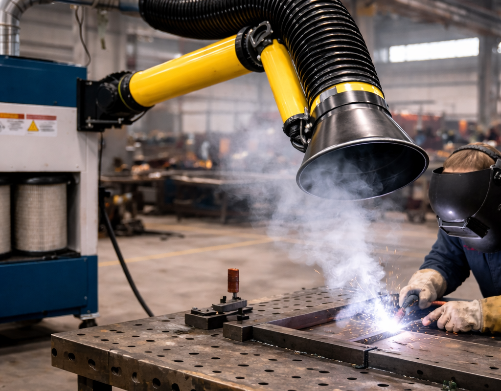
Even the most advanced extraction unit will underperform if the capture point is incorrectly positioned. In welding environments, fumes rise rapidly due to thermal buoyancy and disperse with even minor air currents. If the extraction arm is not placed strategically, fumes bypass the hood and enter the operator’s breathing zone.

Effective welding extraction arm positioning is therefore one of the most critical—and most overlooked—factors in system performance. Many cases of poor ventilation are not caused by inadequate equipment, but by incorrect fume extraction hood placement.

A well-positioned arm enables true source capture welding fumes, ensuring contaminants are removed before dispersion. With over 30 years of experience, Powertech has consistently observed that proper positioning alone can significantly improve welding ventilation efficiency without increasing airflow or system capacity.

Key Takeaways

  1. Correct welding extraction arm positioning is essential for effective fume capture.
  2. Source capture is far more effective than general ventilation.
  3. Hood distance and angle directly impact welding ventilation efficiency.
  4. Small positioning changes can significantly improve system performance.

The Problem: Poor Hood Placement

Improper positioning is one of the leading causes of ineffective welding fume extraction.

Causes

  1. Extraction arm placed too far from the arc
  2. Incorrect angle relative to fume rise direction
  3. Obstruction by the operator or workpiece
  4. Lack of operator training
  5. Frequent repositioning without guidelines

Workplace Impact

  1. Visible fumes escaping into the workspace
  2. Reduced visibility during welding
  3. Increased exposure for operators
  4. Inefficient use of extraction systems

Safety Risks

According to the Occupational Safety and Health Administration (OSHA), exposure to welding fumes can lead to respiratory irritation and long-term health risks.

The National Institute for Occupational Safety and Health (NIOSH) emphasizes source capture as the most effective method for controlling airborne contaminants.

Technical Explanation: How to Position Extraction Arms Correctly

Step 1: Maintain Optimal Distance

The hood should be positioned close enough to capture fumes effectively.

  1. Ideal distance: 150 – 300 mm from the welding arc
  2. Closer positioning reduces airflow requirements

Doubling the distance can significantly reduce capture efficiency.

Step 2: Align with Fume Direction

Welding fumes typically rise upward due to heat.

  1. Position hood slightly above the arc
  2. Angle it to intercept the rising plume

Avoid placing the hood below the welding point.

Step 3: Avoid Blocking Airflow

Improper placement can cause fumes to pass through the operator’s breathing zone.

  1. Do not position hood behind the welder
  2. Avoid placing the hood directly between the arc and the operator’s face

The hood should capture fumes before they reach the operator.

Step 4: Maintain Stable Positioning

Flexible arms must be properly adjusted and locked.

  1. Ensure the arm does not drift during operation
  2. Use arms with good positional stability

Step 5: Minimize Cross Draft Effects

External air movement can disrupt capture.

  1. Avoid placing hoods near fans or open doors
  2. Position to counter airflow disturbances

Recommended Positioning Guidelines

ParameterRecommended ValueRemarks
Hood distance150 – 300 mmCritical for capture
Hood angle30° – 60° toward plumeAlign with fume rise
Position relative to operatorIn front of plumeAvoid breathing zone
Height above arcSlightly aboveMatches fume movement
StabilityFixed positionPrevents drift

Practical Industrial Applications

Fabrication Shops

  1. Frequent repositioning required
  2. Operator training is critical
  3. Flexible arms preferred

Automotive Manufacturing

  1. Fixed positioning in robotic cells
  2. Enclosed extraction systems
  3. Consistent placement improves reliability

Maintenance Workshops

  1. Portable systems used
  2. High dependency on operator positioning

Heavy Engineering

  1. Larger workpieces
  2. Requires adjustable and extended arms

Expert Insight

From Powertech’s field experience, incorrect positioning is one of the most common and easiest-to-fix issues in welding ventilation systems.

In many workshops, improving welding extraction arm positioning has resulted in immediate improvements in air quality without any changes to system capacity.

Key practical observations:

  1. Source capture is more effective than increasing airflow
  2. Proper positioning reduces energy consumption
  3. Operator training is as important as system design

In several installations, correcting fume extraction hood placement has improved efficiency by over 25% without additional investment.

What is the ideal position for a welding extraction arm?

The hood should be placed 150–300 mm from the welding arc and aligned with the direction of rising fumes.

Why is source capture important in welding?

It prevents fumes from spreading into the workspace and reduces operator exposure.

Can poor positioning reduce system efficiency?

Yes, incorrect positioning can significantly reduce capture efficiency even with high airflow.

Should the hood be placed above or below the welding arc?

It should be placed slightly above the arc to capture rising fumes.

How can operators improve positioning?

By keeping the hood close to the source, aligning it with fume direction, and avoiding airflow obstruction.

Conclusion

Proper welding extraction arm positioning is a fundamental requirement for effective fume control. Without correct placement, even well-designed systems fail to capture fumes efficiently. By focusing on source capture welding fumes, optimizing fume extraction hood placement, and improving welding ventilation efficiency, industries can achieve safer and more efficient working environments. With decades of experience, Powertech emphasizes that correct positioning—combined with sound engineering design—is key to achieving reliable and effective welding fume extraction performance.

Duct Design for Welding Fume Extraction Systems

Introduction

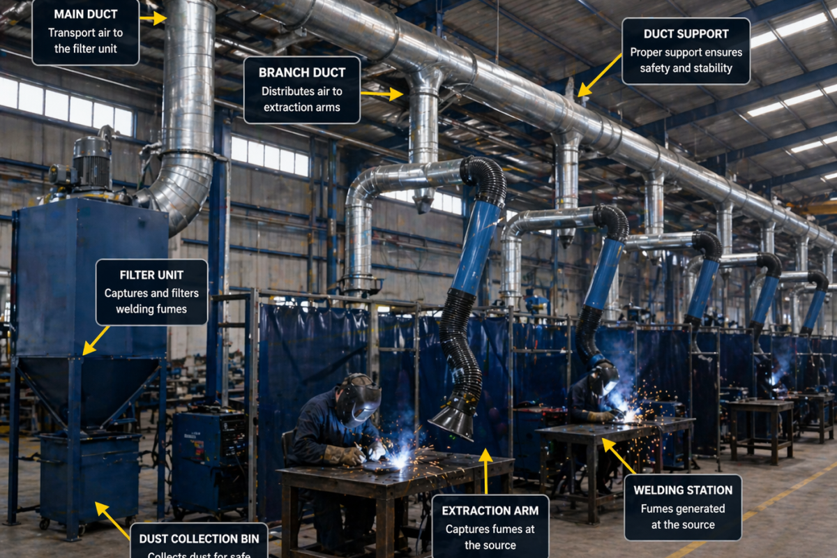
In welding fume control, the extraction unit often gets the most attention—but in practice, system performance is governed just as much by the duct network that connects capture points to the collector. Poorly designed ducting leads to pressure losses, uneven airflow distribution, dust settling, and ultimately ineffective fume capture at the source.

A robust welding fume extraction duct design ensures that the airflow calculated at the hood actually reaches the filtration unit with minimal losses. This requires careful consideration of duct velocity, layout geometry, branch balancing, and material selection. In many workshops, suboptimal industrial ventilation duct design is the root cause behind persistent ventilation issues, even when high-capacity collectors are installed.

With over three decades of field experience, Powertech has optimized fume extraction system layout across fabrication shops, automotive plants, and heavy engineering facilities—where correcting duct design alone has significantly improved system efficiency without increasing fan capacity.

Key Takeaways

  1. Effective welding fume extraction duct design minimizes pressure loss and maintains airflow to all stations.
  2. Proper duct velocity prevents particulate settling and blockages.
  3. Balanced branching is critical for uniform extraction across multiple points.
  4. Layout simplicity (fewer bends, shorter runs) improves overall welding exhaust system design performance.

The Problem: Inefficient Duct Networks

Many ventilation systems underperform due to poor duct design rather than insufficient airflow.

Causes

  1. Excessive bends and long duct runs
  2. Incorrect duct diameter selection
  3. Poor airflow balancing across branches
  4. Low duct velocity causing dust settlement
  5. Leakage due to poor fabrication or joints

Workplace Impact

  1. Uneven fume extraction across stations
  2. Visible smoke in certain areas
  3. Frequent duct clogging
  4. Increased maintenance downtime

Safety Risks

According to the Occupational Safety and Health Administration (OSHA), inadequate ventilation can expose workers to hazardous airborne contaminants.

The American Conference of Governmental Industrial Hygienists (ACGIH) recommends proper duct design practices to ensure effective contaminant transport and control.

Technical Explanation: Key Principles of Duct Design

Step 1: Maintain Proper Duct Velocity

Duct velocity must be high enough to keep particles suspended.

Recommended range:

  1. 10 – 15 m/s for welding fumes

Lower velocity leads to dust settling and clogging.

Step 2: Select Correct Duct Diameter

Duct size directly affects airflow and velocity.

Q = A × V

Where:

  1. Q = Airflow (m³/s)
  2. A = Cross-sectional area (m²)
  3. V = Velocity (m/s)

Larger ducts reduce velocity; smaller ducts increase pressure loss.

Step 3: Minimize Pressure Losses

Pressure loss occurs due to:

  1. Friction in straight ducts
  2. Bends and fittings
  3. Entry and exit losses

Best practices:

  1. Use smooth interior ducts
  2. Minimize bends
  3. Use long-radius elbows

Step 4: Optimize Duct Layout

A good fume extraction system layout should:

  1. Use the shortest possible duct routes
  2. Avoid unnecessary branches
  3. Maintain gradual transitions

Simple layouts perform better than complex ones.

Step 5: Balance Airflow Across Branches

In multi-point systems:

  1. Ensure equal airflow distribution
  2. Use dampers for balancing
  3. Avoid overloading one branch

Poor balancing leads to uneven extraction.

Recommended Design Parameters

Parameter Recommended Range Remarks
Duct velocity 10 – 15 m/s Prevents particle settling
Static pressure 800 – 2000 Pa Depends on system size
Bend radius ≥ 2 × duct diameter Reduces pressure loss
Branch angle ≤ 45° Improves airflow distribution
Leakage tolerance <5% Ensures efficiency

Practical Industrial Applications

Fabrication Shops

  1. Flexible layouts
  2. Multiple extraction arms
  3. Need for adaptable duct routing

Automotive Manufacturing

  1. Large centralized systems
  2. Long duct runs
  3. Requires precise balancing

Maintenance Workshops

  1. Smaller duct systems
  2. Focus on simplicity and flexibility

Heavy Engineering

  1. High particulate load
  2. Requires high-velocity ducting

Expert Insight

From Powertech’s field experience, one of the most overlooked aspects of welding exhaust system design is duct layout simplicity.

In many installations, improving duct routing—reducing bends and optimizing branch connections—has resulted in significant performance gains without increasing fan capacity.

Key practical lessons:

  1. Airflow efficiency is lost more in ducts than in collectors
  2. Balanced systems outperform oversized systems
  3. Good duct design reduces both energy consumption and maintenance
What is the ideal duct velocity for welding fume extraction?

Typically between 10–15 m/s to prevent particle settling.

Why is duct design important in welding ventilation?

Because it ensures that airflow reaches all extraction points efficiently without losses.

Can poor duct design reduce system performance?

Yes, it can lead to pressure losses, uneven airflow, and ineffective fume capture.

How can duct pressure loss be minimized?

By reducing bends, using smooth ducts, and optimizing layout design.

What is the role of dampers in duct systems?

Dampers help balance airflow across multiple branches in the system.

Conclusion

Duct design is a critical component of any welding fume extraction system. Even the most advanced extraction units cannot perform effectively without a well-engineered duct network. A proper welding fume extraction duct design ensures efficient airflow transport, minimizes pressure losses, and maintains consistent extraction performance across all stations. By applying sound industrial ventilation duct design principles and optimizing fume extraction system layout, industries can significantly improve system efficiency and reliability. With decades of experience, Powertech continues to emphasize engineering-driven duct design as a key factor in achieving effective and long-lasting welding exhaust system design solutions.

engineer measuring airflow for welding fume extractor in industrial workshop

Welding Fume Extractor Airflow Calculation Guide

Introduction

Accurate airflow design is one of the most critical aspects of any welding fume extraction system. Undersized systems fail to capture fumes effectively, while oversized systems lead to unnecessary energy consumption and operational costs. In industrial workshops, improper airflow design is one of the leading causes of poor fume control performance.

The key to an efficient system lies in understanding welding fume extractor airflow calculation, which depends on factors such as capture velocity, hood design, and distance from the source. Without proper calculation, even high-quality systems may fail to deliver the required performance.

A well-engineered approach to welding ventilation airflow ensures that fumes are captured at the source before they disperse into the workspace. With decades of experience, Powertech has designed systems where precise fume extraction airflow design has significantly improved air quality and system efficiency across fabrication and manufacturing environments.

Key Takeaways

  • Accurate welding fume extractor airflow calculation is essential for effective fume capture.
  • Capture velocity welding is the most important parameter in determining airflow requirements.
  • Airflow depends on hood design, distance from source, and welding intensity.
  • Proper airflow design improves both safety and energy efficiency.

The Problem: Incorrect Airflow Design

Many workshops face issues due to incorrect airflow calculations during system design.

Causes

  • Lack of understanding of capture velocity requirements
  • Incorrect hood sizing
  • Ignoring distance between hood and welding arc
  • Poor duct design and airflow losses

Workplace Impact

  • Ineffective fume capture
  • Smoke accumulation in work areas
  • Increased operator exposure
  • Reduced system efficiency

Safety Risks

According to the Occupational Safety and Health Administration (OSHA), inadequate ventilation can result in exposure to hazardous welding fumes, affecting respiratory health.

The National Institute for Occupational Safety and Health (NIOSH) emphasizes the importance of proper ventilation design to control airborne contaminants effectively.

Technical Explanation: Airflow Calculation Method

Step 1: Understand Capture Velocity

Capture velocity is the air speed required to draw fumes into the extraction hood.

V = Q / A

Where:

  • V = Capture velocity (m/s)
  • Q = Airflow rate (m³/s)
  • A = Area of hood opening (m²)

Step 2: Determine Hood Area

Calculate the area of the extraction hood opening.

For a circular hood:

A = πr2

Ex: r = 500mm = 0.5m

A = πr2 ≈ 0.79m2

C = 2πr ≈ 3.14m2

For a rectangular hood:

A = L × W

Step 3: Calculate Required Airflow

Rearranging the formula:

Q = V × A

This gives the airflow required for effective fume capture.

Step 4: Adjust for Distance

Airflow requirements increase significantly with distance from the source.

  • At 150 mm → standard airflow
  • At 300 mm → airflow requirement may double

Airflow is directly proportional to the square of the distance of the extraction hood from the fume generation source.

Step 5: Account for System Losses

Include additional airflow to compensate for:

  • Duct losses
  • Filter resistance
  • System inefficiencies

Typical design practice:

  • Add 20–30% safety margin

Example Airflow Calculation

Assume:

  • Hood diameter = 300 mm → radius = 0.15 m
  • Required capture velocity = 1 m/s

Step 1: Area

A = π × (0.15)2 = 0.0707m2

Step 2: Airflow

Q = 1 × 0.0707 = 0.0707 m3/s

Convert to m3/hr:

Q = 0.0707 × 3600 = 254.5 m3/hr

  • Final airflow requirement ≈ 250–300 m3/hr (minimum)
  • After adding losses: 300 – 400 m3/hr per extraction point

Recommended Airflow Parameters

Parameter

Recommended Range

Remarks

Capture velocity

0.5 – 1.5 m/s

Depends on welding type

Airflow per arm

800 – 1500 m³/hr

Industrial standard

Hood distance

150 – 300 mm

Critical for efficiency

Duct velocity

10 – 15 m/s

Prevents dust settling

Safety margin

+20–30%

For system losses

Practical Industrial Applications

Fabrication Shops

  • Flexible extraction arms
  • Variable airflow requirements
  • Need for adaptable systems

Automotive Manufacturing

  • High airflow centralized systems
  • Robotic welding requiring consistent airflow

Maintenance Workshops

  • Portable systems
  • Lower airflow but high positioning dependency

Heavy Engineering

  • High fume loads
  • Requires high-capacity airflow systems

Expert Insight

From Powertech’s experience, the biggest mistake in airflow design is assuming that higher airflow always leads to better performance.

In reality:

  • Poor hood positioning cannot be compensated by increasing airflow
  • Oversized systems waste energy without improving efficiency
  • Proper calculation and design outperform trial-and-error approaches

In several installations, optimizing airflow based on correct capture velocity welding principles has improved system efficiency without increasing system capacity.

Frequently Asked Questions

What is the ideal airflow for a welding fume extractor?

Typically between 800–1500 m³/hr per extraction arm, depending on application.

What is capture velocity in welding ventilation?

It is the air speed required to capture fumes at the source before dispersion.

Does hood size affect airflow requirements?

Yes, larger hood openings require higher airflow to maintain the same capture velocity.

Can airflow be reduced if the hood is closer?

Yes, reducing the distance improves capture efficiency and lowers airflow requirements.

Why is airflow calculation important?

It ensures effective fume capture while optimizing energy consumption.

Conclusion

Accurate welding fume extractor airflow calculation is fundamental to designing effective ventilation systems. Without proper calculation, systems either fail to capture fumes or operate inefficiently.

By understanding welding ventilation airflow, applying correct capture velocity welding principles, and optimizing fume extraction airflow design, industries can achieve efficient fume control and improved air quality.

With decades of experience, Powertech emphasizes engineering-based airflow design to ensure reliable, efficient, and cost-effective welding fume extraction systems.

properly positioned welding fume extraction system improving ventilation in workshop

How to Fix Welding Fume Extraction Problems in Workshops

Introduction

Many industrial workshops invest in fume extraction systems but still struggle with poor air quality, visible smoke, and inconsistent system performance. These issues are typically not due to the absence of equipment, but rather improper system design, incorrect usage, or lack of maintenance. As a result, common welding fume extraction problems persist despite the presence of ventilation systems.

Fixing these issues requires a structured engineering approach that focuses on source capture, airflow optimization, and system configuration. Simply increasing airflow or upgrading equipment without addressing the root cause often leads to inefficient results.

A well-designed strategy to fix welding fume extraction problems involves improving welding air pollution control, correcting design flaws, and implementing proper welding ventilation solutions. Based on over 30 years of experience, Powertech has successfully optimized systems across fabrication shops, automotive facilities, and heavy engineering environments by focusing on practical, application-specific improvements.

Key Takeaways

  • Most welding fume extraction problems can be resolved through proper system optimization rather than replacement.
  • Improving poor welding ventilation requires correct hood positioning and airflow balancing.
  • Addressing fume extraction system design mistakes significantly enhances performance.
  • Regular monitoring and maintenance are critical for effective welding air pollution control.

The Problem: Persistent Fume Extraction Issues

Workshops often experience recurring ventilation issues even after installing extraction systems.

Common Causes

  • Incorrect positioning of extraction arms
  • Insufficient airflow at the source
  • Poor duct design and airflow imbalance
  • Use of undersized or mismatched systems
  • Lack of maintenance and filter clogging

Workplace Impact

  • Smoke accumulation in work areas
  • Reduced visibility and operator comfort
  • Increased contamination of equipment
  • Lower productivity due to poor working conditions

Safety Risks

Exposure to welding fumes poses significant health concerns.
According to the Occupational Safety and Health Administration (OSHA), welding fumes may contain toxic substances that can affect the respiratory and nervous systems.

The National Institute for Occupational Safety and Health (NIOSH) states that prolonged exposure to welding fumes can lead to lung function impairment and other occupational health issues.

Technical Explanation: How to Fix Welding Fume Extraction Problems

Step 1: Optimize Hood Positioning

Position the extraction arm or hood closer to the welding arc.

  • Ideal distance: 150–300 mm
  • Align airflow with fume direction
  • Avoid placing the hood behind the welder

This alone can significantly improve capture efficiency.

Step 2: Improve Airflow and Capture Velocity

Ensure adequate airflow at the point of extraction.

  • Increase airflow where necessary
  • Maintain consistent suction across all stations
  • Verify capture velocity (0.5–1.5 m/s)

Increasing airflow without proper positioning is ineffective.

Step 3: Correct Duct Design Issues

Optimize ducting to reduce pressure losses.

  • Minimize sharp bends
  • Maintain proper duct velocity (10–15 m/s)
  • Balance airflow across all branches

Poor duct design is a major cause of uneven extraction.

Step 4: Match System Type to Application

Use the correct system for the workload.

  • Portable systems for flexible, low-load applications
  • Centralized systems for multiple stations
  • Hybrid setups for mixed environments

Incorrect system selection leads to persistent performance issues.

Step 5: Maintain Filters and System Components

Regular maintenance ensures consistent performance.

  • Monitor pressure drop across filters
  • Replace clogged filters promptly
  • Inspect fans and ducting regularly

Neglecting maintenance reduces system efficiency significantly.

Key Performance Parameters for Effective Welding Ventilation Solutions

Parameter

Recommended Range

Remarks

Capture distance

150 – 300 mm

Critical for source capture

Capture velocity

0.5 – 1.5 m/s

Ensures effective suction

Airflow per arm

800 – 1500 m³/hr

Based on welding intensity

Duct velocity

10 – 15 m/s

Prevents particle settling

Filter efficiency

Up to 99%

Multi-stage filtration

Practical Industrial Applications

Fabrication Workshops

Common issues:

  • Poor positioning of extraction arms
  • Variable workflows

Fix:

  • Use flexible extraction arms
  • Train operators on correct positioning

Automotive Workshops

Common issues:

  • Uneven airflow in centralized systems

Fix:

  • Balance duct networks
  • Integrate extraction into robotic cells

Maintenance and Repair Workshops

Common issues:

  • Incorrect use of portable systems

Fix:

  • Ensure proper placement
  • Select adequate capacity units

Heavy Engineering Facilities

Common issues:

  • High fume loads exceeding system capacity

Fix:

  • Upgrade system capacity
  • Optimize airflow distribution

Expert Insight

From Powertech’s experience across multiple industries, the most effective improvements often come from simple corrections rather than major system upgrades.

In several workshop installations, repositioning extraction arms and balancing airflow has improved system performance by over 30% without increasing equipment capacity.

Key practical lessons:

  • Source capture is more important than airflow volume
  • System design must match real-world usage
  • Regular performance checks are essential

Workshops that treat fume extraction as an engineering system rather than a standalone product achieve significantly better results.

Frequently Asked Questions

How can welding fume extraction problems be fixed?

By optimizing hood positioning, improving airflow, correcting duct design, and maintaining system components.

Why does poor welding ventilation persist even after installing systems?

Because systems are often incorrectly designed, positioned, or maintained.

Is increasing airflow enough to solve fume extraction issues?

No. Proper positioning and system design are equally important.

Can existing systems be improved without replacement?

Yes. Most issues can be resolved through optimization and minor modifications.

How often should welding ventilation systems be checked?

Regular inspections and monitoring of airflow and filter conditions are recommended.

Conclusion

Welding fume extraction systems are essential for maintaining safe and efficient workshop environments, but many facilities continue to face performance issues due to design and operational shortcomings.

Fixing these welding fume extraction problems requires a structured approach that focuses on source capture, airflow optimization, and proper system configuration. By addressing poor welding ventilation and correcting fume extraction system design mistakes, workshops can significantly improve air quality and operational efficiency.With decades of experience in welding air pollution control, Powertech emphasizes the importance of practical, engineering-driven solutions that are tailored to real-world workshop conditions, ensuring reliable and long-term performance.