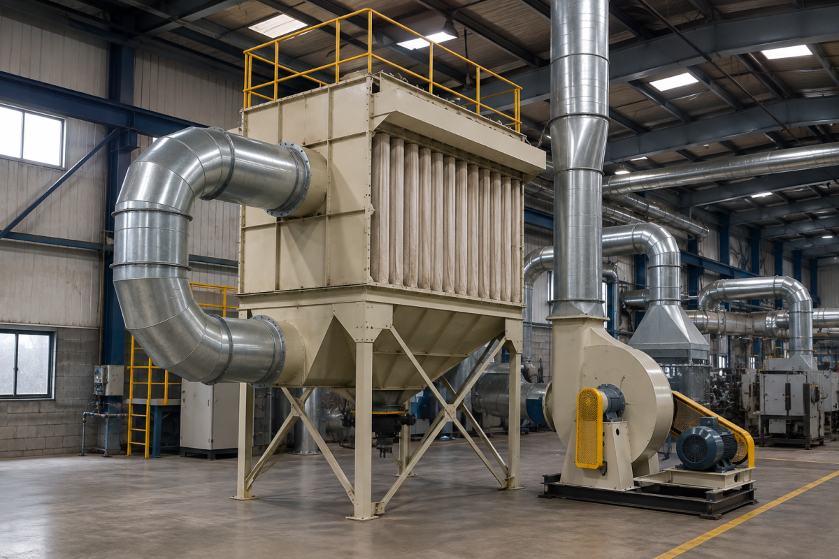
Dust Collector Airflow and CFM Calculation

Introduction

Selecting the correct airflow capacity is one of the most important steps when designing an industrial dust collection system. An undersized system may fail to capture dust effectively, while an oversized system can increase energy consumption, equipment costs, and operating expenses.

Understanding dust collector airflow calculation helps manufacturers determine how much air a dust collection system needs to move to effectively capture and transport airborne contaminants. The required airflow is commonly expressed in CFM (cubic feet per minute) and depends on factors such as the dust-generating process, hood design, capture velocity, ductwork, number of extraction points, and system configuration.

For manufacturers planning a new installation or upgrading an existing system, understanding dust collection CFM, industrial ventilation airflow, and dust collector sizing provides a useful starting point for system design.

Powertech Pollution Controls engineers dust collection systems based on the characteristics of the application rather than simply selecting a collector based on machine size or motor capacity.

Key Takeaways

  1. CFM represents the volume of air moved by a dust collection system.
  2. Required airflow depends on the capture point, dust characteristics, hood design, and ductwork.
  3. Capture velocity is different from duct transport velocity.
  4. Multiple extraction points require careful airflow and system balancing.
  5. Correct dust collector sizing improves capture efficiency and reduces unnecessary energy consumption.
  6. A complete engineering assessment should be performed before selecting the final collector and blower.

What Is Dust Collector CFM?

CFM, or cubic feet per minute, measures the volume of air that a dust collection system moves through its extraction network.

In simple terms:

Higher CFM = greater volume of air moved per minute.

However, higher CFM does not automatically mean better dust collection.

The system must generate sufficient airflow at the point of dust generation and maintain appropriate airflow throughout the ductwork.

This is why dust collector sizing should consider the complete extraction system rather than only the collector’s rated airflow.

The Basic Dust Collector Airflow Calculation

For a simple extraction point, airflow can be estimated using the relationship between capture area and capture velocity:

CFM = Capture Area × Capture Velocity × 60

Where:

  1. CFM = airflow requirement in cubic feet per minute
  2. Capture Area = effective capture area in square feet
  3. Capture Velocity = required air velocity in feet per second
  4. 60 = conversion from seconds to minutes

Example

Suppose an extraction hood has an effective capture area of 1 square foot and the process requires a capture velocity of 100 feet per minute.

The approximate airflow requirement would be:

CFM = 1 × 100 = 100 CFM

In real industrial systems, however, the calculation must account for hood geometry, distance from the contaminant source, duct losses, fittings, filters, and other system resistance.

Capture Velocity vs Duct Velocity

These two terms are often confused during dust collection system design.

Capture Velocity

Capture velocity is the air velocity required at the source to pull airborne dust into the extraction hood.

The required value depends heavily on the process.

A relatively calm dust-generating operation may require less capture velocity than a high-energy grinding, cutting, or material-transfer process.

Duct Transport Velocity

Duct velocity refers to the velocity required to transport captured dust through the ductwork without allowing particles to settle.

The required transport velocity depends on:

  1. Dust particle size
  2. Dust density
  3. Moisture
  4. Material characteristics
  5. Duct orientation
  6. Process conditions

Therefore, airflow should never be selected solely from the capture hood requirement.

Factors That Affect Dust Collection CFM

1. Type of Dust

Different materials behave differently in an extraction system.

Examples include:

  1. Fine metal dust
  2. Wood dust
  3. Plastic particles
  4. Food powders
  5. Chemical powders
  6. Mineral dust
  7. Grinding dust

Particle size, density, moisture, and abrasiveness all influence system design.

2. Dust-Generating Process

The energy of the process affects how aggressively contaminants are released.

Processes such as:

  1. Grinding
  2. Cutting
  3. Sanding
  4. Polishing
  5. Mixing
  6. Crushing
  7. Material transfer

may require substantially different extraction approaches.

3. Hood Design

The hood is one of the most important components of the system.

A poorly designed or incorrectly positioned hood can require substantially more airflow to achieve effective capture.

Source capture generally provides better efficiency than attempting to remove dust after it has dispersed throughout the facility.

4. Distance From the Dust Source

As the distance between the extraction point and dust source increases, the airflow requirement generally increases.

This is why extraction hoods should be positioned as close to the emission point as practical.

5. Number of Extraction Points

A system serving one machine will have very different airflow requirements from a centralized system serving ten or twenty machines.

The design must determine:

  1. Which points operate simultaneously
  2. Required airflow at each point
  3. Diversity of operation
  4. Branch duct dimensions
  5. Main duct capacity

Calculating Airflow for Multiple Machines

Suppose a manufacturing facility has four extraction points:

Extraction PointRequired Airflow
Grinding machine1,500 CFM
Cutting machine1,200 CFM
Sanding station900 CFM
Material transfer point700 CFM

If all four operate simultaneously:

Total airflow = 1,500 + 1,200 + 900 + 700

Total = 4,300 CFM

However, the final dust collector and blower should not automatically be selected at exactly 4,300 CFM.

The system designer must also evaluate duct losses, filter resistance, fittings, hood performance, operating conditions, and the possibility that not all extraction points operate simultaneously.

Understanding Static Pressure

CFM tells you how much air the system moves.

Static pressure tells you how much resistance the blower must overcome to move that air.

A dust collector therefore needs both:

  1. Adequate airflow
  2. Adequate pressure capability

Resistance can come from:

  1. Extraction hoods
  2. Ductwork
  3. Elbows
  4. Branches
  5. Dampers
  6. Filters
  7. Cyclones or pre-separators
  8. Exhaust arrangements

A blower capable of delivering a high CFM at low resistance may not deliver the required airflow once connected to a long, complex duct network.

Dust Collector Sizing: What Should Be Considered?

Correct dust collector sizing requires more than selecting a filter based on airflow.

Engineers should evaluate:

Dust Characteristics

  1. Particle size
  2. Density
  3. Moisture
  4. Temperature
  5. Abrasiveness
  6. Combustibility

Process Conditions

  1. Production rate
  2. Operating hours
  3. Dust generation rate
  4. Number of machines
  5. Simultaneous operation

System Requirements

  1. Required CFM
  2. Static pressure
  3. Duct length
  4. Number of bends
  5. Filter type
  6. Dust discharge arrangement

Why Oversizing a Dust Collector Isn’t Always Better

It may seem logical to select the largest available dust collector, but excessive airflow can create unnecessary costs.

Potential disadvantages include:

  1. Higher fan power consumption
  2. Larger ductwork
  3. Higher initial equipment cost
  4. Greater filter area requirements
  5. Increased operating costs
  6. Excessive airflow at individual machines

The objective should be adequate airflow at the correct pressure, not simply maximum airflow.

Why Undersizing Is a Problem

An undersized dust collection system can result in:

  1. Poor dust capture
  2. Dust escaping into the workplace
  3. Dust settling inside ductwork
  4. Filter overload
  5. Increased maintenance
  6. Reduced equipment life
  7. Poor workplace air quality

In severe cases, inadequate airflow can cause the entire collection system to perform poorly even when the dust collector itself is functioning correctly.

Industrial Ventilation Airflow vs Dust Extraction

General industrial ventilation airflow and localized dust extraction serve different purposes.

General Ventilation

Moves and replaces air throughout the facility.

Local Dust Extraction

Captures contaminants directly where they are generated.

For manufacturing processes that generate concentrated dust emissions, local exhaust ventilation is generally the more effective approach for contaminant control.

General ventilation can complement source extraction, but it should not automatically be considered a replacement for properly designed dust collection.

How Duct Design Affects CFM

Ductwork has a major influence on dust collection performance.

Poor duct design can create:

  1. Excessive pressure losses
  2. Uneven airflow
  3. Dust accumulation
  4. Higher fan energy consumption
  5. Poor capture at remote extraction points

Important design considerations include:

  1. Duct diameter
  2. Branch arrangement
  3. Elbow configuration
  4. Duct length
  5. Air velocity
  6. Balancing dampers
  7. Transition geometry

A properly engineered duct network ensures that the required airflow reaches each extraction point.

Signs That Your Dust Collector May Be Undersized

Existing systems may show several warning signs:

Visible Dust Escaping

Dust remains airborne even when the extraction system is operating.

Weak Suction

Operators notice inadequate airflow at extraction hoods.

Dust Accumulation in Ducts

Particles settle because transport velocity is insufficient.

Frequent Filter Loading

Filters become clogged faster than expected.

Inconsistent Performance

Some machines extract effectively while others perform poorly.

These symptoms can indicate airflow, static pressure, duct design, filter loading, or system balancing problems.

How Powertech Approaches Dust Collector Sizing

Powertech does not recommend selecting a dust collector based solely on a machine’s dimensions or motor rating.

A properly engineered system considers:

  1. Dust-generating process
  2. Dust characteristics
  3. Number of extraction points
  4. Required capture conditions
  5. Airflow requirements
  6. Duct network
  7. Static pressure
  8. Filtration requirements
  9. Dust discharge requirements
  10. Future production requirements

This application-specific approach helps ensure that the resulting DustBag system delivers reliable extraction without unnecessarily increasing energy or equipment costs.

What is dust collector airflow calculation?

Dust collector airflow calculation is the process of determining the amount of air required to capture and transport airborne dust effectively through an extraction system.

How is dust collection CFM calculated?

For a basic extraction point, airflow can be estimated from the effective capture area and required capture velocity. Complete industrial calculations must also consider hood design, ductwork, filter resistance, static pressure, and process conditions.

What does CFM mean in dust collection?

CFM means cubic feet per minute and represents the volume of air moved by the dust collection system.

Is higher CFM always better?

No. The system needs sufficient airflow at the required static pressure. Excessive airflow can increase energy consumption and equipment costs without improving dust capture.

How do I determine the correct dust collector size?

Dust collector sizing requires evaluation of dust characteristics, process conditions, number of extraction points, required airflow, ductwork, static pressure, filtration requirements, and operating conditions.

Can one dust collector serve multiple machines?

Yes. A centralized dust collection system can serve multiple machines when the collector, blower, ductwork, and control system are properly engineered for the required operating conditions.

Conclusion

Accurate dust collector airflow calculation is essential for designing an effective industrial dust extraction system. While CFM provides a useful measure of airflow capacity, proper dust collection CFM calculations must be combined with capture velocity, duct transport requirements, static pressure, filtration resistance, and the characteristics of the dust-generating process. Correct dust collector sizing is therefore an engineering exercise rather than simply selecting the largest available unit. By designing the hood, ductwork, blower, filtration system, and dust collector as one integrated system, manufacturers can achieve reliable dust capture, better workplace air quality, and more efficient long-term operation. Powertech’s engineering team can evaluate the specific process, airflow requirements, and plant layout to develop a DustBag industrial dust collection system suited to the application’s actual operating conditions.
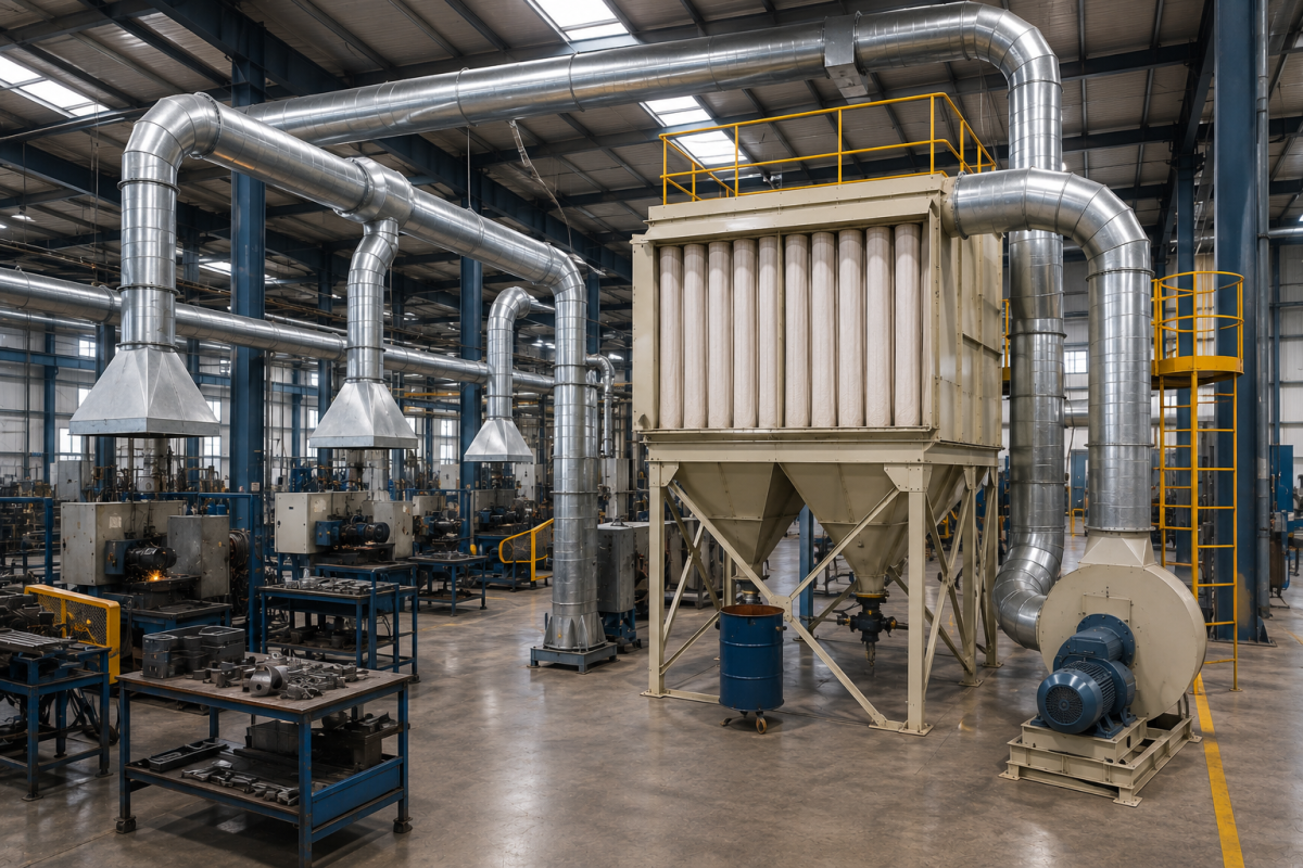
Dust Collection System Design for Manufacturing Plants

Introduction

Manufacturing processes such as grinding, cutting, sanding, polishing, mixing, material handling, and machining can generate significant quantities of airborne dust. Without proper control, these contaminants can spread throughout a production facility, settle on machinery, affect product quality, increase housekeeping requirements, and reduce workplace air quality.

An effective dust collection system design captures dust as close as possible to the point of generation and transports it through a properly engineered extraction network to a filtration system. The performance of the complete system depends not only on the dust collector itself, but also on hood design, airflow, ductwork, static pressure, filtration, and dust discharge.

A properly engineered industrial dust extraction system can therefore provide substantially better results than simply installing a high-capacity dust collector and connecting it to existing ductwork.

For manufacturing facilities, the objective should be to design a complete factory dust control system around the actual processes, dust characteristics, operating conditions, and future production requirements.

Key Takeaways

  1. Effective dust collection begins with source capture.
  2. Dust collector capacity should be determined from airflow and static-pressure requirements.
  3. Hood and duct design are just as important as the filtration unit.
  4. Different manufacturing processes require different extraction strategies.
  5. Proper system balancing ensures consistent airflow across multiple machines.
  6. A well-designed system reduces dust contamination, maintenance, and energy waste.

What Is Dust Collection System Design?

Dust collection system design is the engineering process of determining how airborne dust will be captured, transported, filtered, and discharged from a manufacturing facility.

A complete system generally consists of:

  1. Source-capture hoods
  2. Extraction ductwork
  3. Dampers and branches
  4. Dust collector
  5. Filtration media
  6. Exhaust blower
  7. Dust discharge system
  8. Electrical and control systems

Each component must work together.

A high-performance dust collector cannot compensate for poorly designed hoods, undersized ductwork, excessive pressure losses, or inadequate airflow.

Step 1: Identify the Dust Sources

The first stage is to identify every process generating airborne contaminants.

Common sources include:

  1. Grinding machines
  2. Cutting machines
  3. Sanding stations
  4. Polishing equipment
  5. CNC machining
  6. Mixing systems
  7. Crushing equipment
  8. Material transfer points
  9. Powder handling
  10. Packaging machinery

The design should document the location and operating conditions of each source.

Step 2: Understand the Dust Characteristics

Not all dust behaves the same way.

Before selecting an industrial dust extraction system, engineers should evaluate:

  1. Particle size
  2. Particle density
  3. Dust concentration
  4. Moisture content
  5. Temperature
  6. Abrasiveness
  7. Chemical properties
  8. Combustibility

Fine powder may require a different filtration strategy from coarse metal particles or abrasive mineral dust.

Step 3: Select the Right Capture Method

Source capture is generally the most effective approach because it removes dust before it disperses into the facility.

Depending on the process, capture may involve:

Enclosed Extraction

The machine or process is partially or completely enclosed.

This is often highly effective because the extraction system controls the contaminant within a defined area.

Extraction Hood

A hood is positioned close to the dust-generating operation.

Downdraft Extraction

Air is drawn downward through a work surface, capturing dust generated during operations such as grinding or finishing.

Side-Draft Extraction

Air is pulled horizontally across the process toward an extraction opening.

Canopy Hood

Used where contaminants rise naturally and where other source-capture arrangements are impractical.

The capture method should be selected based on the process rather than simply using the same hood configuration throughout the plant.

Step 4: Determine Required Airflow

Airflow is one of the most important parameters in dust collection system design.

The required airflow depends on:

  1. Hood dimensions
  2. Capture distance
  3. Process energy
  4. Dust characteristics
  5. Number of extraction points
  6. Simultaneous operation

Airflow is typically expressed in CFM (cubic feet per minute).

The system must provide sufficient airflow at each extraction point while also maintaining adequate transport velocity through the ductwork.

Simply choosing a collector with a high CFM rating does not guarantee effective extraction.

Step 5: Design the Ductwork

Ductwork connects individual extraction points to the central collector.

Poorly designed ductwork can result in:

  1. Excessive pressure loss
  2. Uneven airflow
  3. Dust settling
  4. Increased fan energy consumption
  5. Poor extraction at remote machines

The design should consider:

  1. Duct diameter
  2. Duct length
  3. Air velocity
  4. Number of branches
  5. Elbow configuration
  6. Transitions
  7. Dampers
  8. Main duct arrangement

Smooth, properly sized duct routing generally provides better system performance than unnecessarily complicated layouts.

Step 6: Calculate Static Pressure

A dust collection blower must overcome the resistance created by the entire system.

Pressure losses can occur through:

  1. Hoods
  2. Ductwork
  3. Elbows
  4. Branches
  5. Dampers
  6. Filters
  7. Cyclones
  8. Exhaust outlets

The blower therefore needs to be selected based on the required airflow at the system’s operating static pressure.

Selecting a fan based solely on its maximum CFM rating can result in inadequate performance once the system is installed.

Step 7: Select the Dust Collector

The filtration unit should be selected according to the dust and process conditions.

Common technologies include:

Cartridge Dust Collectors

Suitable for many fine, dry dust applications where a compact system and high filtration surface area are advantageous.

Baghouse Dust Collectors

Suitable for high dust loading, high airflow, and many heavy industrial applications.

Cyclone Pre-Separators

Often used to remove larger particles before they reach the primary filtration stage.

The appropriate technology depends on the application rather than simply the desired airflow.

Step 8: Consider Dust Discharge

Collected dust needs to be removed reliably from the system.

Possible arrangements include:

  1. Collection bins
  2. Hoppers
  3. Rotary airlocks
  4. Screw conveyors
  5. Continuous discharge systems
  6. Automated material handling

The discharge method should match the volume and characteristics of the collected dust.

Step 9: Design for Multiple Machines

Manufacturing facilities frequently require a centralized factory dust control system serving multiple machines.

For these systems, engineers must determine:

  1. Total airflow
  2. Individual branch airflow
  3. Simultaneous operation
  4. Diversity factor
  5. Main duct dimensions
  6. Branch balancing
  7. Fan capacity

For example, a facility may have ten machines connected to one collector, but not all ten may operate simultaneously.

Designing around actual production conditions can prevent unnecessary oversizing while maintaining adequate extraction.

Step 10: Balance the System

A centralized system must be balanced so that each extraction point receives the required airflow.

Without proper balancing, some machines may experience:

  1. Excessive suction
  2. Insufficient suction
  3. Uneven dust capture

Balancing dampers and properly designed branch ductwork can help distribute airflow appropriately.

Manufacturing Dust Ventilation vs Local Exhaust

General manufacturing dust ventilation and local exhaust serve different purposes.

General Ventilation

Controls overall room air conditions by replacing or diluting contaminated air.

Local Exhaust

Captures contaminants directly at their source.

For dust-generating manufacturing processes, local exhaust is generally the primary control strategy. General ventilation can complement source capture but should not be relied upon to remove concentrated dust emissions after they have dispersed.

Common Dust Collection Design Mistakes

Using the Collector CFM as the Only Design Parameter

A collector’s rated CFM does not describe the performance of the complete system.

Poor Hood Placement

If the hood is too far from the dust source, substantially more airflow may be required.

Undersized Ductwork

Small ducts can create excessive pressure losses and restrict airflow.

Excessive Duct Bends

Unnecessary elbows and complicated routing increase system resistance.

Ignoring Static Pressure

A blower must be capable of delivering the required airflow against the actual system resistance.

Designing Without Future Expansion

A system designed only for today’s production may become inadequate as new machines are added.

Designing for Energy Efficiency

An efficient dust collection system does not necessarily mean using the largest possible blower.

Energy consumption can be reduced through:

  1. Correctly sized ductwork
  2. Efficient hood design
  3. Proper system balancing
  4. Variable-frequency drives where appropriate
  5. Automatic dampers
  6. Filter monitoring
  7. Maintaining clean filtration media

The objective is to deliver the required airflow at the required pressure with minimum unnecessary resistance.

Designing for Future Expansion

Manufacturing facilities often expand over time.

A good dust collection system design should consider potential:

  1. Additional machines
  2. Increased production
  3. New extraction points
  4. Extended operating hours
  5. Process changes

Providing appropriate provisions for future expansion can be considerably more economical than replacing the entire system later.

Powertech’s Approach to Dust Collection System Design

Powertech approaches industrial dust extraction as a complete system rather than simply supplying a dust collector.

The design process considers:

  1. Dust-generating processes
  2. Dust characteristics
  3. Capture method
  4. Required airflow
  5. Ductwork configuration
  6. Static pressure
  7. Filtration technology
  8. Dust discharge
  9. Fan selection
  10. Plant layout
  11. Maintenance requirements
  12. Future expansion

This application-specific approach allows DustBag systems to be configured for the actual operating conditions of the manufacturing facility.

What is the most important factor in dust collection system design?

Effective source capture is one of the most important factors. Dust should ideally be captured as close as possible to where it is generated before it disperses into the workplace.

How is an industrial dust extraction system sized?

Sizing depends on required airflow, capture conditions, dust characteristics, number of extraction points, ductwork, static pressure, filtration requirements, and operating conditions.

Can one dust collector serve an entire factory?

Yes. Centralized systems can serve multiple machines and production areas when the collector, blower, ductwork, and controls are correctly engineered.

Is general factory ventilation enough for dust control?

Generally, no. General ventilation can supplement local extraction, but source capture is normally more effective for controlling concentrated dust emissions.

What happens if a dust collection system is undersized?

An undersized system may provide insufficient airflow, resulting in poor dust capture, dust accumulation, filter overload, increased maintenance, and reduced workplace air quality.

Should a dust collection system be designed for future expansion?

Yes. Where future production growth is expected, the system should be designed with appropriate capacity and provisions for additional extraction points.

Conclusion

Effective dust collection system design requires much more than selecting a dust collector with a suitable CFM rating. The complete industrial dust extraction system must integrate source capture, airflow, ductwork, static pressure, filtration, dust discharge, and fan selection into a coordinated system. For manufacturing facilities, a properly engineered factory dust control system provides more consistent dust capture, cleaner production areas, reduced equipment contamination, and better energy efficiency. General manufacturing dust ventilation can complement the system, but localized source extraction should remain the foundation for controlling dust generated by industrial processes. Powertech’s engineering-led approach to DustBag systems enables manufacturers to develop customized dust collection solutions based on their actual processes, operating conditions, and future production requirements.