
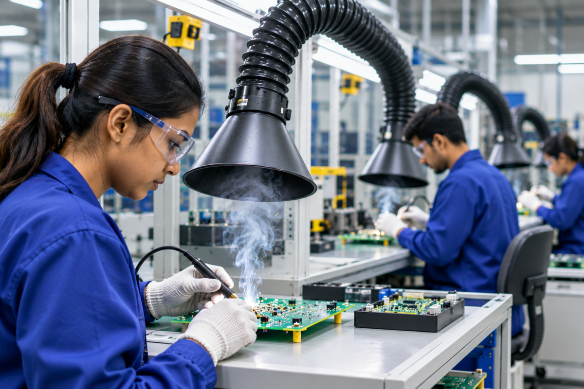
Printed circuit board (PCB) assembly involves several soldering operations, from manual component installation and rework to automated wave and selective soldering. While these processes are essential to electronics manufacturing, they also generate airborne emissions that need to be controlled through properly designed ventilation.
Flux vapours, fine particulate matter, and other process-related emissions can accumulate around soldering workstations when extraction is inadequate. In facilities with multiple assembly lines, relying on general room ventilation alone may not provide effective control at the points where fumes are generated.
A properly designed PCB soldering fume extractor system should capture emissions close to their source, transport contaminated air through a suitable duct network, and filter it using technology appropriate to the process.
However, designing ventilation for an electronics plant involves more than selecting extraction equipment. The system must account for different soldering processes, workstation layouts, production volumes, simultaneous operating requirements, airflow distribution, filtration, and maintenance access.
This guide explains the key design considerations for PCB soldering fume extraction and how electronics manufacturers can plan an effective ventilation arrangement for their facilities.
Why PCB Assembly Plants Need Dedicated Fume Extraction
Soldering emissions are generated when flux and other process materials are heated during soldering. Depending on the flux formulation and operating conditions, the emissions can contain fine airborne particles and gaseous compounds.
The nature and quantity of emissions vary with the soldering method, materials, process temperature, and production rate.
Several characteristics of electronics manufacturing make dedicated extraction particularly important.
1. Multiple Soldering Processes Under One Roof
A typical PCB assembly plant may have several different operations running simultaneously:
- Manual soldering and component installation
- PCB repair and rework
- Wave soldering
- Selective soldering
- Automated soldering processes
- Inspection and testing stations involving occasional soldering
Each operation has a different emission source and may require a different capture arrangement.
For example, manual soldering typically involves individual workstations where a nozzle or flexible extraction arm can be positioned near the soldering point. Wave soldering equipment may require extraction integrated with its enclosure or process hood.
A single extraction arrangement should not automatically be assumed suitable for every operation.
2. Continuous Production and Multiple Operators
Electronics manufacturing facilities often operate several assembly stations throughout the working day. In high-volume production, multiple operators may solder components simultaneously across several lines.
Even when emissions from an individual station are relatively limited, the combined load from multiple active workstations can become significant.
The extraction system must therefore be designed around the number of operating stations, production schedules, and expected simultaneous demand.
3. Closely Spaced Workstations
PCB assembly areas frequently have compact workstation layouts. Operators work close to circuit boards, soldering irons, inspection equipment, and other tools.
If extraction hoods are poorly positioned or airflow is inadequate, fumes may pass through the operator’s breathing zone before being captured.
Effective PCB assembly ventilation should intercept emissions before they disperse into the surrounding workspace.
4. Changing Production Requirements
Electronics manufacturers may introduce new products, modify PCB designs, add assembly stations, or change soldering processes.
An extraction system designed only for the initial workstation layout may become inadequate as production changes.
Planning for future expansion, accessible duct connections, and available extraction capacity can make the ventilation system easier to adapt.
Identify the Fume Sources Before Designing the System
The first step in designing PCB fume extraction is to identify where emissions are generated and how each process operates.
A plant-level assessment should distinguish between the different soldering activities rather than treating the entire assembly area as one uniform extraction zone.
Manual PCB Soldering
Manual soldering is commonly performed at individual workbenches. Operators use soldering irons to attach components, connectors, wires, and other electronic parts to circuit boards.
A localized extraction nozzle or flexible arm can be positioned close to the soldering point to capture rising emissions.
The capture arrangement should allow operators to work comfortably without obstructing their hands, tools, or view of the PCB.
PCB Rework and Repair
Rework stations involve removing, replacing, or modifying components on existing circuit boards.
Unlike repetitive assembly operations, rework activities may involve different board sizes, component positions, and soldering techniques.
Flexible extraction arms or adjustable capture nozzles are useful where the capture position needs to change frequently.
Wave Soldering
Wave soldering is an automated process in which circuit boards pass over a wave of molten solder. Flux is applied before soldering, and the heating process can generate emissions that need to be captured.
The extraction arrangement should be integrated with the equipment enclosure or an appropriately designed hood.
The design must account for conveyor openings, access panels, equipment geometry, and the airflow needed to prevent emissions from escaping into the production area.
Selective Soldering
Selective soldering applies molten solder to specific areas of a PCB. Depending on the equipment, the process may involve flux application, preheating, and localized soldering.
Extraction should be coordinated with the machine’s enclosure and operating cycle. The capture arrangement must remove emissions without interfering with the process or disturbing any required shielding or thermal conditions.
Choose the Right Fume Capture Arrangement
The capture method is one of the most important decisions in PCB soldering ventilation design.
The objective is to intercept fumes close to where they are generated, before they spread through the workstation or production area.
Localized Extraction at Individual Workstations
For manual soldering and repair operations, localized extraction is often a practical solution.
A nozzle, hood, or flexible extraction arm is positioned near the soldering point. The fan draws contaminated air into the extraction system, preventing emissions from dispersing freely around the operator.
This arrangement is particularly suitable for:
- Individual PCB assembly benches
- Electronics repair departments
- Prototype and testing areas
- Rework stations
- Small production sections with changing workstation requirements
The extraction point should remain close enough to the soldering operation to capture emissions effectively. It should also be positioned so that it does not interfere with the operator’s work.
Powertech’s soldering workstation fume extraction design guide explains how capture positioning, workstation layout, and operator ergonomics influence extraction performance.
Machine-Integrated Extraction
Automated soldering equipment may require extraction integrated with its enclosure or process hood.
This is particularly relevant for wave soldering and selective soldering machines, where emissions can be generated inside an enclosed or partially enclosed process area.
The extraction design should consider:
- Equipment enclosure dimensions
- Conveyor and component entry and exit openings
- Location of the flux application and soldering zones
- Access requirements for cleaning and maintenance
- Airflow required during different process stages
The objective is to remove emissions without creating excessive air movement that could interfere with the process.
Centralized Extraction for Multiple Workstations
For larger electronics plants, several soldering stations may be connected to a common extraction and filtration unit through a duct network.
A centralized system can be useful when:
- Multiple workstations operate in a fixed production layout.
- Several extraction points require continuous service.
- A common maintenance location is preferred.
- The facility has suitable space for duct routing and central equipment.
However, the system must be engineered around the required airflow at each station and the number of stations expected to operate simultaneously.
A centralized arrangement is not automatically the most economical or effective choice. The decision should account for installation cost, ductwork, operating hours, pressure losses, and maintenance requirements.
Powertech’s Soldering Fume Extractor solutions provide further information on individual and centralized extraction arrangements for electronics manufacturing applications.
Airflow Design for PCB Soldering Fume Extraction
Airflow is a critical factor in determining whether a soldering fume extraction system can capture emissions effectively.
The required airflow depends on the capture arrangement, hood dimensions, distance from the emission source, duct resistance, and number of operating extraction points.
A system should not be selected simply by comparing the maximum airflow ratings of different extractors.
Airflow at Each Workstation
Every extraction point should receive sufficient airflow for its intended capture arrangement.
For manual soldering, the position and design of the extraction nozzle are particularly important. A nozzle placed too far from the soldering point may allow fumes to escape before they reach the intake.
The airflow should also be appropriate for the working environment. Excessive suction can create discomfort, interfere with lightweight components, or affect the movement of fumes around the workstation.
Total Airflow for Multiple Stations
When several soldering stations are connected to a centralized system, the design must account for their combined demand.
The total requirement depends on:
- Number of extraction points
- Required airflow at each point
- Number of points operating simultaneously
- Branch duct configuration
- System pressure losses
- Airflow balancing arrangements
It is important to distinguish between the total number of installed extraction points and the number expected to operate at the same time.
A system serving 30 stations does not necessarily need to operate all 30 at their maximum design airflow continuously. However, the assumed operating schedule must reflect actual production conditions.
Static Pressure and Duct Design
Static pressure represents the resistance that the fan must overcome as air moves through the extraction network.
In a centralized PCB fume extraction system, pressure losses occur across:
- Extraction nozzles and hoods
- Duct bends and fittings
- Branch connections
- Dampers and balancing devices
- Filters and other system components
Ductwork should be sized and routed to maintain the required airflow at the extraction points.
Long duct runs, unnecessary bends, and poorly designed branch connections can increase resistance and affect overall performance.
Where multiple stations operate simultaneously, airflow balancing may be necessary to prevent some workstations from receiving significantly more extraction than others.
Selecting the Right Filtration Technology
Capturing soldering emissions is only one part of the ventilation system. The collected air must also pass through filtration suitable for the contaminants generated by the process.
The filtration arrangement should be selected after reviewing the solder and flux materials, process conditions, and expected emissions.
Particulate Filtration
Soldering can generate fine airborne particles that require suitable particulate collection.
Electrostatic filtration is one technology used in industrial soldering fume extraction. It works by electrically charging airborne particles and collecting them on oppositely charged collection plates.
Powertech’s Fumekiller® uses a two-stage electrostatic filtration arrangement for capturing fumes and fine particulate matter. Its collection modules are designed to be reusable, subject to appropriate cleaning and maintenance.
Activated Carbon for Odour Control
Some soldering processes generate gaseous compounds and odours associated with heated flux.
Activated carbon can be considered as an additional filtration stage where the application requires adsorption of suitable gaseous contaminants.
However, carbon media should not be treated as a universal solution for every gas or vapour. Its suitability depends on the chemical compounds involved, the type and quantity of media, contact time, and replacement or servicing requirements.
Particulate collection and gas-phase treatment perform different functions. The filtration design should address both where the process requires it.
Fumekiller® for Soldering Applications
Powertech’s Fumekiller® fume extraction system is designed for industrial fume applications, including soldering and welding.
Its electrostatic collection technology is suitable for applications where fine particulate emissions need to be captured. Depending on the application, an additional activated-carbon post-filter can be considered for odour control.
The appropriate configuration depends on the soldering process, number of extraction points, airflow requirements, and contaminant characteristics.
Centralized vs Individual Extraction in PCB Assembly Plants
Electronics manufacturers must decide whether to use independent extraction units at individual workstations or connect several capture points to a centralized system.
Neither arrangement is universally better. The choice depends on production volume, workstation layout, equipment requirements, and maintenance strategy.
Individual extraction can be practical for smaller production areas, repair benches, and workstations that frequently change position. It provides greater independence between stations, although multiple units may increase equipment footprint and maintenance tasks.
Centralized extraction can be suitable for larger production lines with fixed layouts and multiple operating stations. It consolidates the main filtration equipment, but requires careful duct design, airflow balancing, and planning for shared-system downtime.
Some electronics plants may benefit from a hybrid arrangement. For example, a centralized system could serve fixed assembly lines, while independent units support prototype benches and repair areas.
The best configuration should be based on actual operating requirements rather than station count alone.
A Practical Example: Extraction for 60 Soldering Stations
Powertech’s documented installation for a leading power infrastructure manufacturer demonstrates the scale of ventilation planning that may be required in electronics production.
The facility had 60 soldering stations operating throughout the day. The challenge was to control emissions across the workstations while avoiding excessive equipment obstruction and maintenance complexity.
Powertech implemented an arrangement using 30 Fumekiller® FK500IM units, each serving two workstations through twin extraction arms.
The soldering fume extraction case study provides further details about the application.
This example illustrates an important design principle: the number of soldering stations does not automatically determine the number of extraction units required. Capture-point configuration, airflow demand, workstation layout, and operating conditions all influence the final arrangement.
Common PCB Soldering Ventilation Design Mistakes
Even when suitable extraction equipment is installed, poor system design can reduce its effectiveness.
Depending Only on General Room Ventilation
General ventilation helps manage overall indoor air conditions, but it may not capture fumes close to individual soldering operations.
Source capture should be considered wherever emissions are generated at identifiable workstations or process equipment.
Positioning Extraction Hoods Too Far Away
A nozzle or hood placed too far from the soldering point may allow fumes to disperse before they are collected.
Operators should be able to position the capture point close to the work without obstructing the task.
Using the Same Capture Design for Every Process
Manual soldering, PCB rework, wave soldering, and selective soldering have different emission sources and equipment configurations.
The extraction arrangement should be matched to the actual process.
Ignoring Simultaneous Operating Requirements
A centralized system designed without considering how many stations operate together may fail to deliver the required airflow across the production area.
The design should use realistic production schedules and account for peak operating conditions.
Overlooking Maintenance Access
Filters, fans, duct branches, and extraction arms need periodic inspection and servicing.
The equipment layout should allow maintenance personnel to access these components without unnecessary disruption to production.
How to Plan a PCB Assembly Ventilation System
Before selecting equipment, electronics manufacturers should conduct a structured assessment of their production environment.
The following steps provide a practical starting point.
Step 1: Map the Soldering Operations
Identify all soldering processes across the plant, including manual assembly, rework, wave soldering, and selective soldering.
Record where emissions are generated and whether the process is continuous, intermittent, or batch-based.
Step 2: Establish the Number of Extraction Points
Determine how many workstations and machines require extraction.
Also establish how many stations are expected to operate simultaneously during normal and peak production periods.
Step 3: Select the Capture Method
Evaluate whether each operation requires an individual nozzle, flexible extraction arm, machine-integrated hood, or connection to a centralized network.
Step 4: Calculate Airflow and Pressure Requirements
Establish the airflow required at each capture point and calculate the pressure losses through the ductwork and filtration equipment.
For centralized systems, assess the combined demand and airflow distribution across the network.
Step 5: Match Filtration to the Process
Review the flux and solder materials, relevant safety data sheets, and expected contaminants.
Select particulate filtration and any additional gas-phase treatment based on the actual requirements.
Step 6: Plan Installation and Maintenance
Consider duct routing, equipment location, electrical requirements, access for filter servicing, and future expansion.
The system should be commissioned to verify airflow and capture performance under representative production conditions.
PCB soldering can release fine airborne particles and chemical emissions from heated flux and other process materials. A suitable extraction system captures these emissions near their source and filters the collected air to help control workplace exposure.
The appropriate method depends on the operation. Manual soldering and rework may use localized extraction arms or nozzles, while wave and selective soldering machines may require integrated hoods or enclosure extraction. Large production areas may use centralized systems.
Yes. A properly designed centralized system can serve multiple workstations through a duct network. Its fan, filtration capacity, and ductwork must be selected for the required airflow and expected simultaneous operation.
Not in every application. Activated carbon can be useful for adsorbing certain gaseous compounds and odours, but its suitability depends on the contaminants and operating conditions. It does not replace particulate filtration.
Electrostatic filtration is one option for capturing fine particulate emissions. Additional filtration may be appropriate depending on the gaseous contaminants and odour-control requirements. The final configuration should be selected for the actual soldering process.
Both can be suitable. Individual units offer flexibility for smaller or changing workstations, while centralized systems can serve larger fixed production layouts. A hybrid arrangement may also be appropriate.
Effective PCB soldering fume extraction requires a coordinated approach to source capture, airflow, ductwork, and filtration. Electronics plants must consider the differences between manual soldering, rework, wave soldering, and automated processes before selecting an extraction arrangement. For smaller work areas, individual extraction units may provide the flexibility required. Larger production facilities may benefit from centralized extraction, provided the system is properly engineered for simultaneous airflow demand and maintenance requirements. The priority should always be to capture emissions close to where they are generated and select filtration appropriate to the process. Powertech Pollution Controls provides industrial soldering fume extraction solutions for electronics manufacturing applications. Explore the soldering fume extractor solutions from Powertech to understand the available configurations, or review the Fumekiller® system for more information about electrostatic fume filtration.