
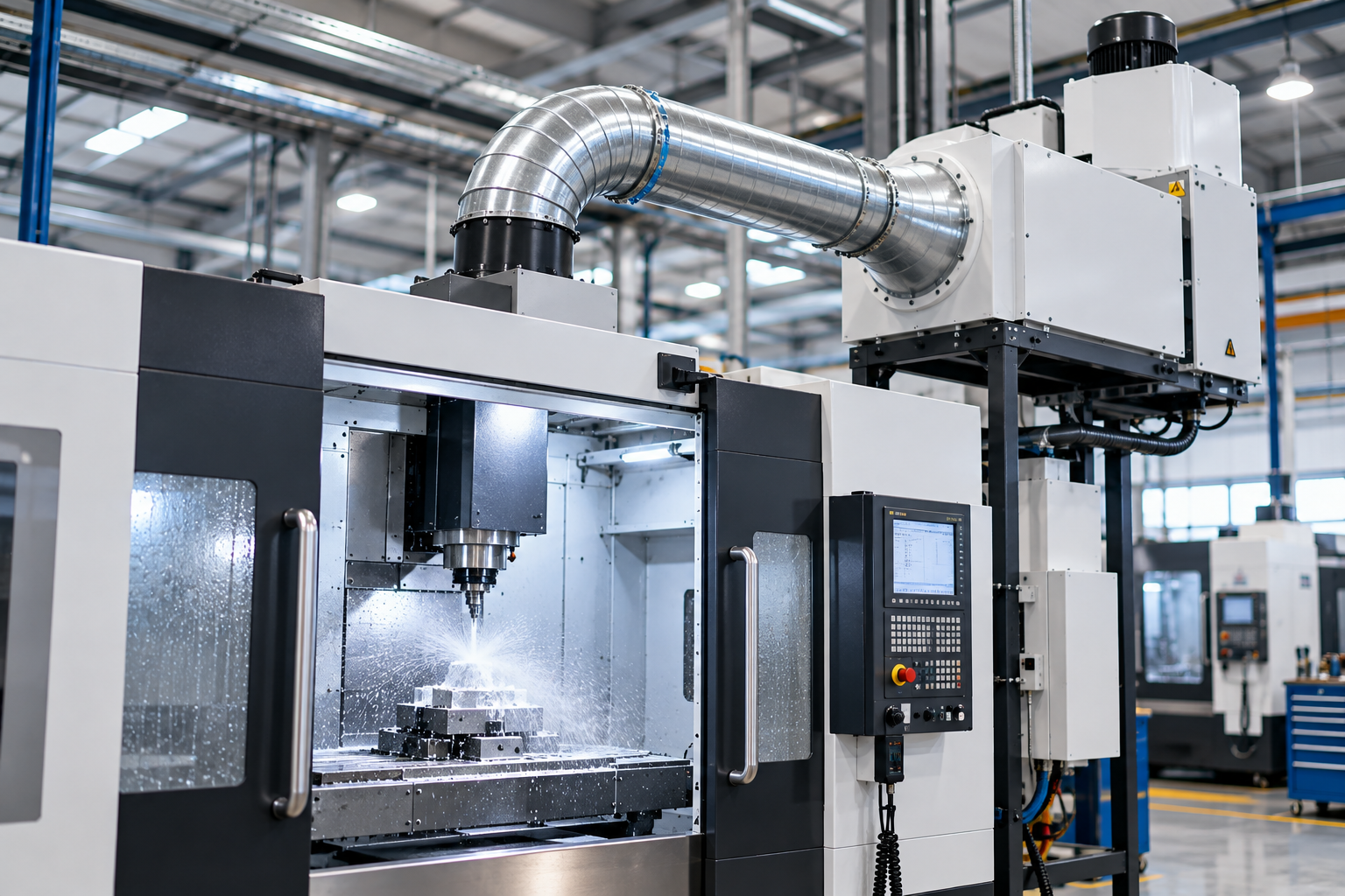
CNC machining operations often generate airborne coolant mist as cutting fluids are sprayed, circulated, and exposed to high-speed machining processes. If this mist is not effectively controlled, it can escape from machine enclosures, accumulate on surrounding surfaces, and affect workplace air quality.
Selecting the right mist collector requires more than matching a machine to a collector’s advertised airflow. Mist collector airflow must be sufficient to capture airborne mist, draw it through the filtration system, and maintain effective extraction under actual machining conditions.
For CNC machine shops, the required airflow depends on enclosure design, coolant type, machining speed, leakage openings, extraction ductwork, and the number of machines connected to the system. A collector designed for one enclosed CNC machine may not be suitable for a larger machine or a centralized installation serving multiple machines.
This guide explains how to evaluate mist collector CFM requirements, calculate airflow, and select a suitable mist extraction system for CNC machining applications.
What Is Mist Collector Airflow?
Mist collector airflow is the volume of air drawn through a mist extraction system over a specified period. It is commonly expressed in cubic feet per minute (CFM) or cubic metres per hour (m³/hr).
In CNC machining, airflow helps remove airborne droplets generated by cutting fluids, coolants, and machining processes. The collector draws contaminated air from the machine enclosure, passes it through an appropriate separation or filtration system, and handles the filtered air according to the installation design.
The required airflow depends on several factors:
- The size and design of the CNC machine enclosure.
- The number and location of openings through which mist can escape.
- The type of machining operation and cutting-fluid application.
- The amount of mist generated during production.
- The extraction connection and ductwork arrangement.
- The resistance created by filters and other system components.
A higher CFM rating does not automatically mean better mist collection. The objective is to maintain the airflow needed to control mist escape without creating unnecessary energy consumption or disrupting the machine’s intended operation.
What Is CFM in a CNC Mist Collector?
CFM stands for cubic feet per minute. It measures the volume of air moving through the mist extraction system each minute.
The term mist collector CFM is useful when comparing equipment, but the rating must be considered alongside the collector’s operating static pressure and the extraction arrangement.
A collector may have a stated maximum airflow when operating with little resistance. Once connected to the CNC machine, ductwork, and filters, the actual airflow can be lower.
For reference:
| Airflow (CFM) | Approximate airflow (m³/hr) |
|---|---|
| 100 | 170 |
| 200 | 340 |
| 300 | 510 |
| 500 | 850 |
| 750 | 1,274 |
| 1,000 | 1,699 |
| 1,500 | 2,549 |
These values are unit conversions, not recommended airflow requirements for particular CNC machines.
The correct CFM must be established from the machine’s extraction requirements, the enclosure configuration, and the pressure losses across the complete system.
Why Is Correct Mist Collector Airflow Important?
1. Controlling Coolant Mist Escape
During CNC turning, milling, drilling, and grinding, coolant can become airborne as droplets or fine mist. Some of this mist remains suspended long enough to escape through enclosure openings when the door opens or when extraction is inadequate.
A properly designed extraction arrangement helps remove airborne mist and limits its release into the surrounding work area.
2. Maintaining Effective Enclosure Extraction
Many CNC machines use enclosed workspaces to contain chips, coolant, and mist. The extraction system must be compatible with the enclosure and its openings.
Insufficient airflow may allow mist to escape. Excessive or poorly directed airflow can also interfere with the intended enclosure airflow, so the design should reflect the machine manufacturer’s requirements.
3. Supporting Reliable Filtration
The collector must draw the contaminated air through its separation and filtration stages at the intended operating conditions.
If airflow falls below the required level, mist capture may deteriorate. If the system operates outside the collector’s specified range, separation performance and operating stability may also be affected.
4. Reducing Unnecessary Operating Costs
Oversizing a collector can increase electricity consumption and may create unnecessary noise. Undersizing can lead to poor mist containment and additional workplace cleaning.
Correct sizing balances capture performance, pressure losses, energy use, and maintenance requirements.
What Determines CNC Mist Collector CFM Requirements?
There is no single CFM value suitable for every CNC machine. Several engineering factors determine the required airflow.
1. CNC Machine Enclosure Size
The dimensions of the machine enclosure are relevant, but enclosure volume alone does not determine the required airflow.
A fully enclosed machining centre with well-controlled openings may have different extraction requirements from a machine with large access openings or frequent door movement.
The design should consider the openings through which mist may escape, the machine’s operating cycle, and the intended direction of airflow.
2. Machining Process and Speed
CNC turning, milling, grinding, and drilling generate different patterns of coolant movement and mist formation.
High-speed machining can produce fine airborne droplets, while grinding may involve different coolant delivery and mist-generation conditions. The effect of cutting speed, coolant delivery, tool geometry, and enclosure design should be considered together.
For this reason, airflow should not be selected solely by the machine’s nominal power or spindle speed.
3. Coolant Type
Coolant characteristics affect mist generation and the selection of the collection equipment.
Water-based coolant mist: Common in machining operations that use water-based emulsions or solutions. A suitable centrifugal mist collector, such as Powertech’s MistKiller mist collector, may be evaluated for compatible applications.
Neat cutting-oil mist: Generated when machining uses oil without dilution in water. The collection method must be selected for the oil mist and the specific process conditions. Powertech positions its FumeKiller range for suitable oil-mist applications.
Water-based coolant mist and neat cutting-oil mist should not automatically be treated as interchangeable. The collection technology must match the liquid, droplet characteristics, operating conditions, and manufacturer’s application limits.
4. Number of Machines Connected
A collector serving one CNC machine has a different airflow requirement from a centralized system serving several machines.
For multiple machines, determine which units operate simultaneously and establish the airflow needed at each extraction point. The combined demand must then be assessed alongside duct resistance, branch balancing, and the collector’s operating capacity.
Simply adding the maximum advertised airflow ratings of several machines or collectors may not produce a reliable system design.
5. Ductwork and Static Pressure
Duct length, diameter, bends, branches, dampers, and filtration components all affect system resistance.
The fan must deliver the required airflow at the pressure needed to overcome these losses. A collector with a high free-air CFM rating may not provide the necessary airflow when connected to a restrictive duct network.
How to Calculate Mist Collector Airflow
The calculation method depends on whether the installation uses a dedicated collector connected directly to a CNC machine or a centralized system serving multiple machines.
Step 1: Establish the Machine’s Extraction Requirement
Start with the CNC manufacturer’s recommendations, the enclosure design, and the intended extraction connection.
Document:
- The machine model and enclosure arrangement.
- The extraction port size and location.
- The coolant type and machining process.
- The expected operating cycle.
- The number and size of enclosure openings.
- Any specified airflow or pressure requirements.
If the manufacturer provides a required airflow range, use it as the starting point and verify that the proposed collector can deliver that airflow under the actual installation conditions.
If no airflow requirement is available, the system should be assessed using the enclosure design, expected mist generation, and appropriate engineering guidance rather than an arbitrary CFM-per-machine rule.
Step 2: Determine the Required Airflow at Each Machine
For a dedicated installation, establish the airflow needed to maintain effective mist extraction at the machine connection.
For a centralized installation, establish the requirement separately for each connected machine.
The airflow requirement should reflect the actual extraction arrangement, including whether the machine operates with its enclosure closed, how often doors open, and how the system handles changes in production demand.
Step 3: Calculate the Combined Airflow Requirement
For a centralized system, add the airflow requirements of the machines expected to operate simultaneously.
For example, assume four CNC machines each require an illustrative 200 CFM at their extraction connections.
If all four machines operate simultaneously, the combined nominal airflow requirement is:
4 × 200 CFM = 800 CFM.
This is an example of arithmetic, not a recommended CFM value for CNC machines. The actual airflow must be established for the specific equipment and enclosure.
The system design must then account for ductwork resistance, branch balancing, and the fan’s performance at the required static pressure.
Step 4: Evaluate Ductwork and Static Pressure
Once the airflow requirement is established, calculate the pressure losses across the system.
These may include:
- Extraction ports and connecting hoses.
- Straight duct sections.
- Elbows, bends, and branch connections.
- Dampers and balancing devices.
- Collector inlets and outlets.
- Filtration or separation stages.
- Exhaust ductwork, where fitted.
The fan must be selected to deliver the required airflow at the calculated operating pressure. Selecting by maximum CFM alone can result in inadequate extraction after installation.
Step 5: Consider Operating Changes and Maintenance
Mist collector performance can be affected by filter condition, liquid loading, maintenance, and changes in machine operation.
Confirm the manufacturer’s operating limits and maintenance requirements. Where applicable, provide a means to check airflow or identify abnormal operating conditions.
The final design should be suitable for the expected production cycle, not just a short test with clean filters and ideal operating conditions.
Mist Collector Airflow vs. Air Velocity
Airflow and air velocity describe different aspects of air movement.
Airflow is the volume of air moving through the system per unit of time.
Air velocity is the speed at which the air moves through a duct or opening.
For a duct with a known cross-sectional area, the relationship is:
[
Q = V x A
]
Where:
- (Q) is volumetric airflow.
- (V) is average air velocity.
- (A) is the duct’s internal cross-sectional area.
When airflow is measured in CFM and velocity in feet per minute, duct area is expressed in square feet.
This relationship can help engineers evaluate duct sizing, but it does not establish the required airflow for a CNC machine by itself. Mist capture is influenced by enclosure openings, the extraction connection, and the behaviour of airborne droplets.
Duct design should be based on the collector manufacturer’s requirements and the installation’s airflow and pressure calculations.
How to Size a Centralized CNC Mist Extraction System
Centralized extraction may be suitable for a facility with several CNC machines, provided the system is designed for the actual operating demand.
A structured design process should include:
- Map the machines: Record each machine’s extraction connection, enclosure configuration, and coolant type.
- Establish simultaneous demand: Determine which machines will operate at the same time.
- Determine branch airflow: Establish the airflow required at each extraction point.
- Design the duct network: Select duct dimensions and branch arrangements to deliver the intended airflow.
- Calculate pressure losses: Assess the resistance along the relevant airflow paths.
- Select the collector and fan: Confirm that the equipment can meet the airflow requirement at the operating pressure.
- Plan balancing and verification: Provide suitable means to check airflow and adjust the system during commissioning.
A centralized system should not be sized using the total number of installed machines alone. Actual operating schedules and simultaneous usage must be considered.
How Mist Collector Technology Affects Airflow Requirements
The required airflow is only one part of collector selection. The separation method must also be appropriate for the coolant and mist characteristics.
Centrifugal Mist Collectors
Centrifugal mist collectors use rotational motion to separate liquid droplets from the airstream. Their suitability depends on the droplet characteristics, coolant, machine application, and the equipment’s specified operating range.
Powertech’s MistKiller centrifugal mist collector is intended primarily for compatible water-based coolant mist applications. The required airflow should be confirmed against the selected model’s technical specifications and the CNC machine’s extraction requirements.
Electrostatic Collection for Oil Mist
Electrostatic mist collection uses an electrical field to collect suitable airborne particles or droplets. Equipment selection must consider the oil characteristics, process conditions, required airflow, and any applicable safety requirements.
Powertech’s FumeKiller extraction range is positioned for suitable oil-mist applications, including processes using neat cutting oil.
The correct technology should be selected from the actual application, not from CFM alone. A collector should not be assumed suitable for both water-based coolant mist and neat cutting-oil mist without confirming its specifications.
Common Mistakes When Sizing CNC Mist Collector Airflow
Choosing a Collector Based Only on Maximum CFM
Maximum airflow may represent performance under conditions that do not match the installed system. Check the airflow available at the required operating static pressure.
Using the Same CFM for Every CNC Machine
Machine enclosure design, coolant delivery, machining process, and operating conditions can change the extraction requirement. Use machine-specific information wherever possible.
Ignoring Ductwork Resistance
Long duct runs, restrictive bends, and poorly balanced branches can reduce airflow at the machine. Include the complete duct network in the design calculations.
Confusing Coolant Mist with Oil Mist
Water-based coolant mist and neat cutting-oil mist can require different collection technologies. Identify the coolant before selecting the collector.
Ignoring Machine Enclosure Conditions
Door openings and enclosure leakage can affect mist containment. The extraction arrangement must be compatible with the way the machine is operated.
Failing to Verify Installed Airflow
After installation, verify that the system delivers the intended airflow at the relevant extraction points. Commissioning checks help identify problems with duct balancing, fan selection, or installation resistance.
CNC Mist Collector Selection Checklist
Before requesting a quotation, prepare the following information:
- CNC machine make and model.
- Machine enclosure dimensions and extraction connection details.
- Coolant type: water-based or neat cutting oil.
- Machining process and operating conditions.
- Manufacturer-specified airflow requirements, if available.
- Number of machines and simultaneous operating demand.
- Duct lengths, diameters, bends, and branch connections.
- Required operating static pressure.
- Collector technology and compatibility with the coolant.
- Maintenance requirements and replacement parts.
- Airflow verification and commissioning requirements.
This information allows suppliers to assess the application and recommend a suitable configuration rather than relying on a generic airflow estimate.
Conclusion
Choosing the right mist collector airflow for CNC machines requires a system-level assessment. CFM is an important specification, but effective extraction also depends on machine enclosure design, coolant type, ductwork resistance, static pressure, and the collector’s separation technology.
For an individual CNC machine, begin with the machine manufacturer’s extraction requirements and verify the airflow available at the installed operating pressure. For centralized installations, calculate the combined demand of simultaneously operating machines and account for ductwork and branch balancing.
Powertech Pollution Controls offers mist and fume extraction solutions for industrial applications. To evaluate a suitable configuration, provide the CNC machine details, coolant type, extraction connection, operating schedule, and proposed installation layout.
The goal is to select a system that captures the intended mist under real machining conditions—not simply one with the highest advertised CFM rating.